WeedWarden
4th Year Capstone Project
This project was our 4th year capstone at the University of Waterloo, earning a 97% and the Best Prototype Award (2nd highest distinction) at the design symposium (I missed the photo below due to a job interview).

We set out to build a “Roomba for your lawn”—a robot that autonomously blends up weeds nightly, eliminating them over time without manual labor or pesticides.
For our final review, we recorded the robot autonomously clearing our test setup. In the first video, it follows a pre-defined path, detects fake weeds, and removes them using computer vision and onboard decision-making. Drill speed and depth are limited for safety.
The next video demonstrates repeatability: the robot completes two autonomous clears of the turf, with weeds placed arbitrarily and the field reset between runs.
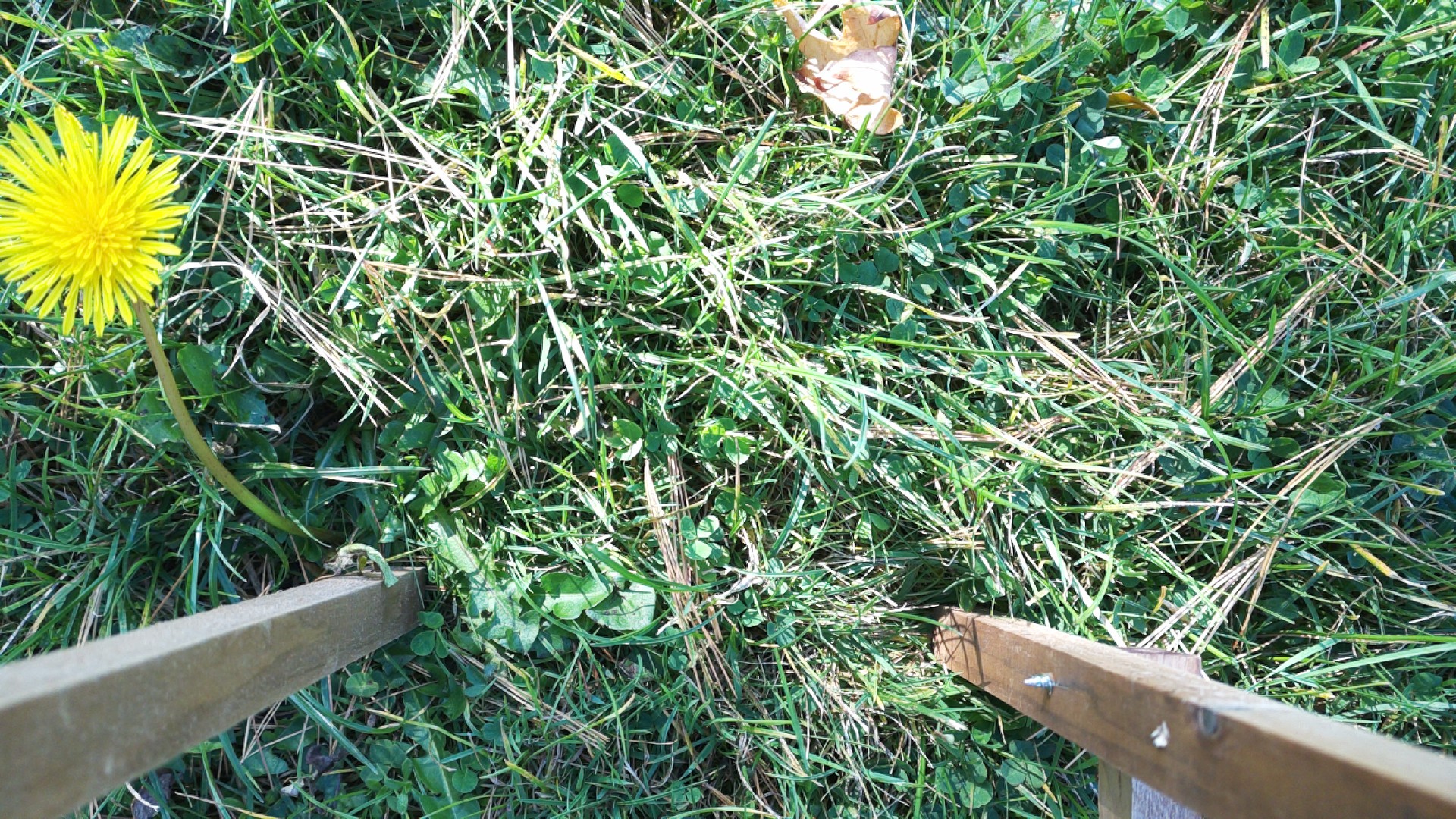
To test real plant removal, we took the robot outside (dandelions were out of season, so we used garden store plants). The robot is manually controlled in this clip, so removal appears choppy; in practice, it would reposition and retry until the weed is gone.
The Project
We began working on this project about a month before the official start of the capstone course, meeting early to brainstorm and refine ideas. Each team member pitched three concepts, and through several voting rounds, we narrowed them down while validating feasibility.
Final contenders included:
- A lake-mapping autonomous boat
- A tattoo robot
- An agricultural robot
- A hull-cleaning robot
We chose the agricultural robot for its complexity and modularity, allowing us to adjust scope as needed. With limited experience in autonomous robotics, this flexibility was key. Weed removal stood out as an approachable, impactful problem that hadn’t been widely commercialized.
To keep development manageable, we split the robot into two main subsystems: the weed removal (cartesian) system for manipulating the end effector, and the locomotion system for moving the robot. We started by focusing on the weed removal system.
The Team
Our core group of four had previously built robots together (see previous project), so we stuck with what worked. Below is a photo of the team at our design symposium.

- Ethan Dau: Electrical lead and project manager. Designed, fabricated, and tested the electrical system, developed firmware for the cartesian system, managed meetings, timeline, budget, and course deliverables.
- Myself: Technical and software lead. Oversaw overall architecture, functional requirements, and technical direction. Wrote all higher-level software, managed device communication, contributed to firmware and mechanical design, and led testing.
- Eric Gharghouri: Designed, fabricated, and tested the locomotion system.
- Varrun Vijayanathan: Mechanical lead. Designed, fabricated, and tested the cartesian system and integrated it with the locomotion system.
Early Design Ideas
The robot was divided into two main subsystems: weed removal and locomotion, each developed independently before integration.
Weed Removal System
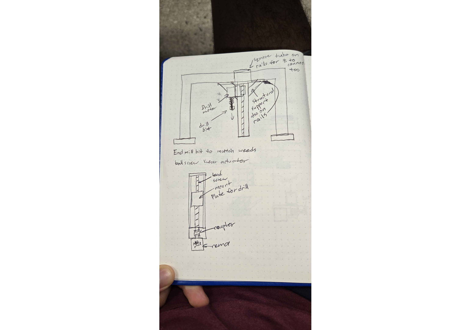
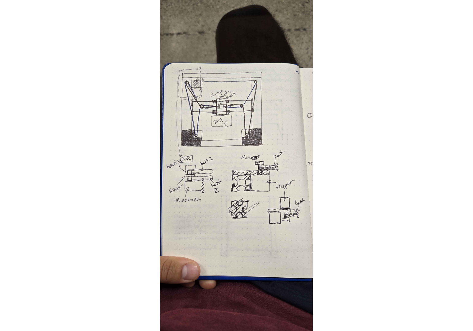
This system had two parts: the cartesian mechanism and the end effector. Below are early sketches of both:
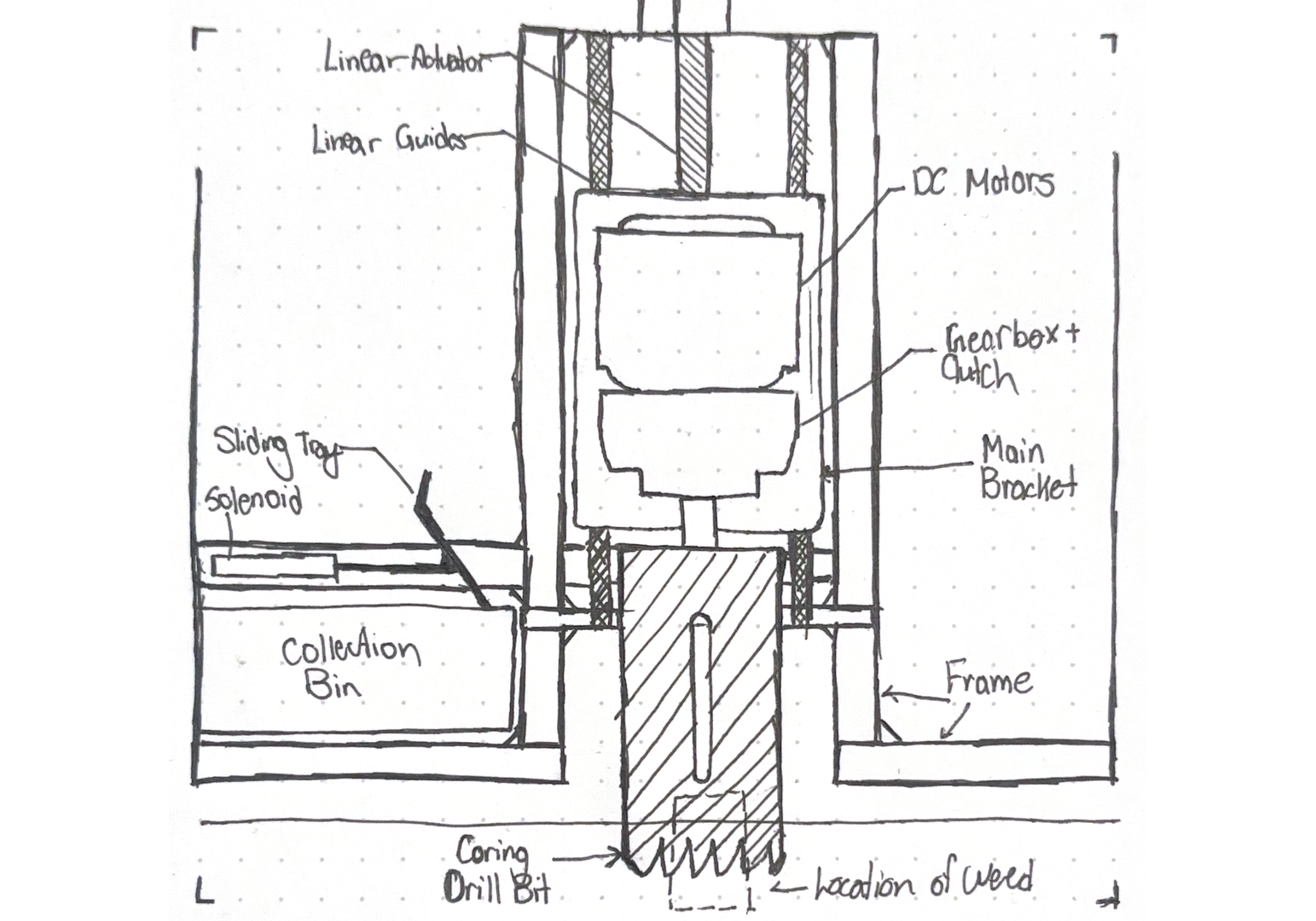
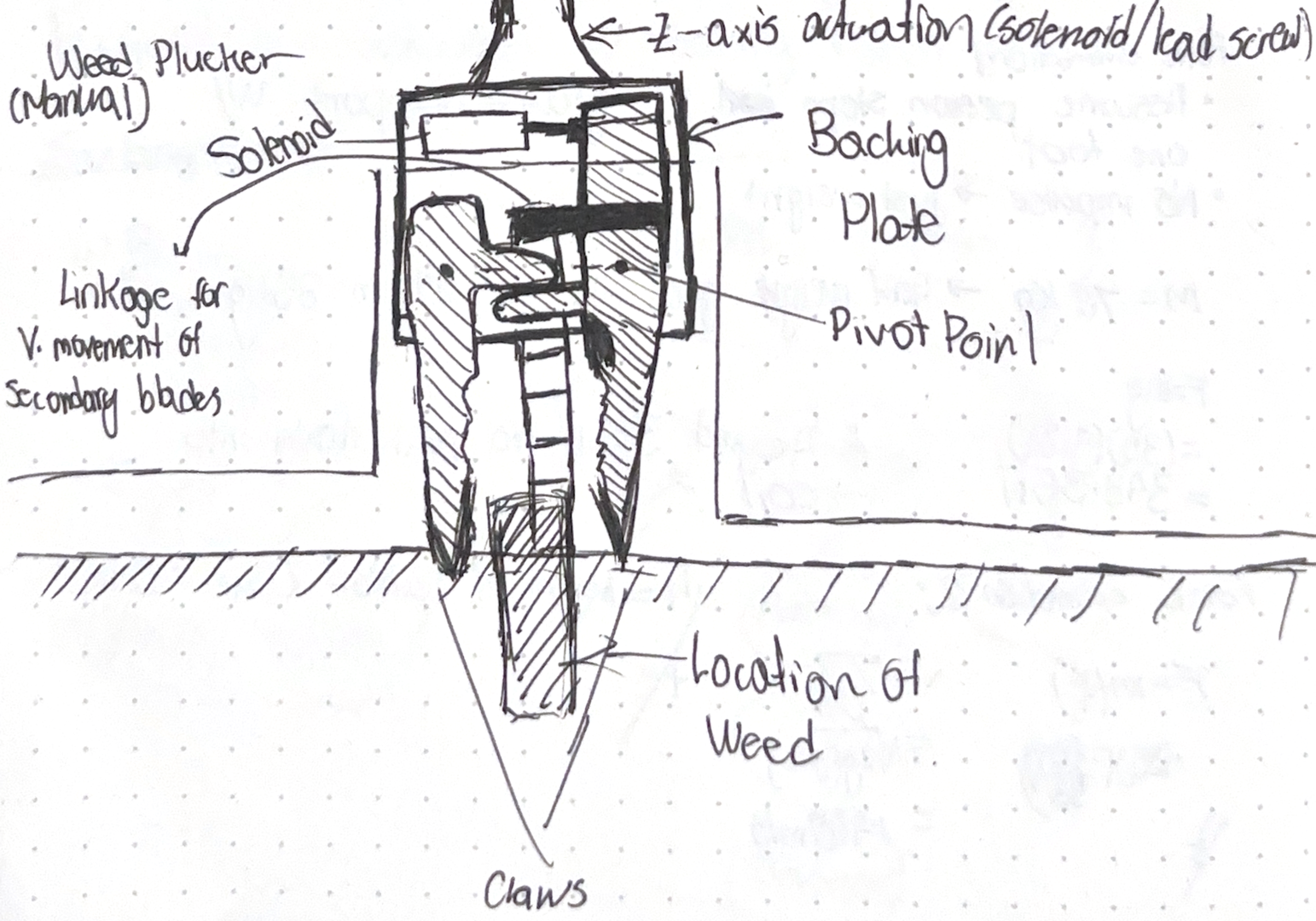
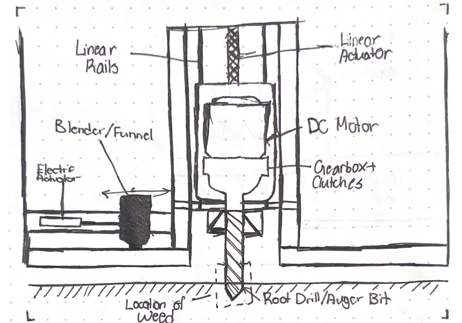
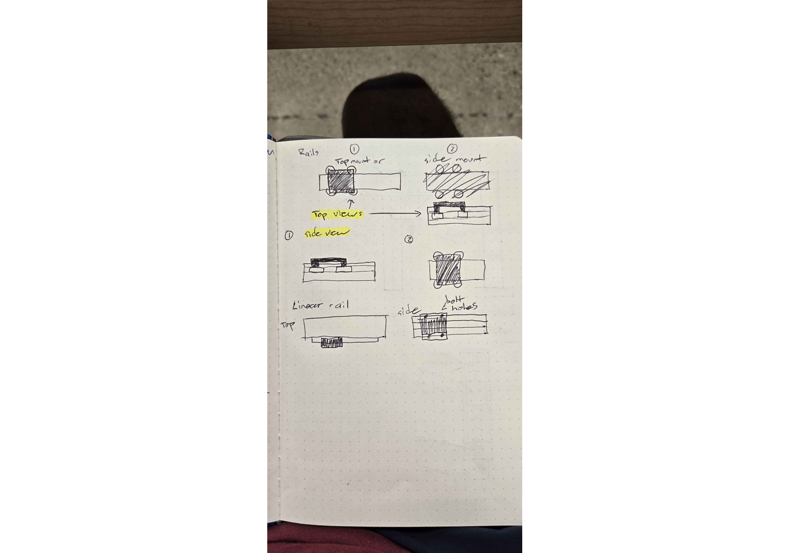
We tested both a pinch method and a coring bit for the end effector. The coring bit was chosen due to lower force requirements, though clearing debris from the bit remained a challenge.
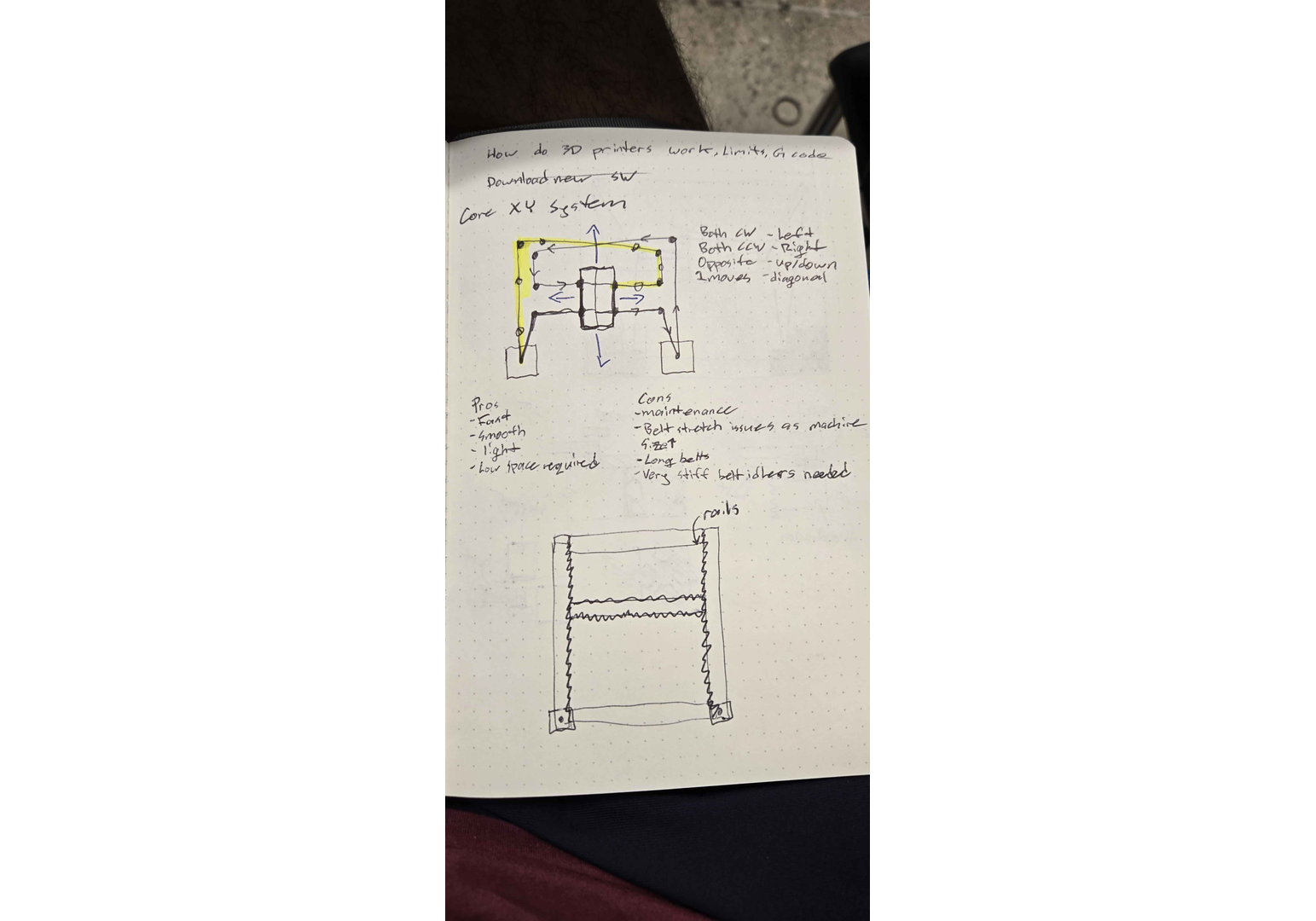
For the cartesian system, we initially considered full 3-axis motion but realized that combining y/z actuation with x-axis movement from the drive system was simpler and more practical for a heavy robot. This hybrid approach reduced complexity and improved maneuverability.
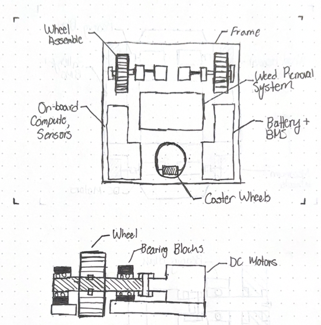
Locomotion System
We explored several classic mobile robot drive trains:
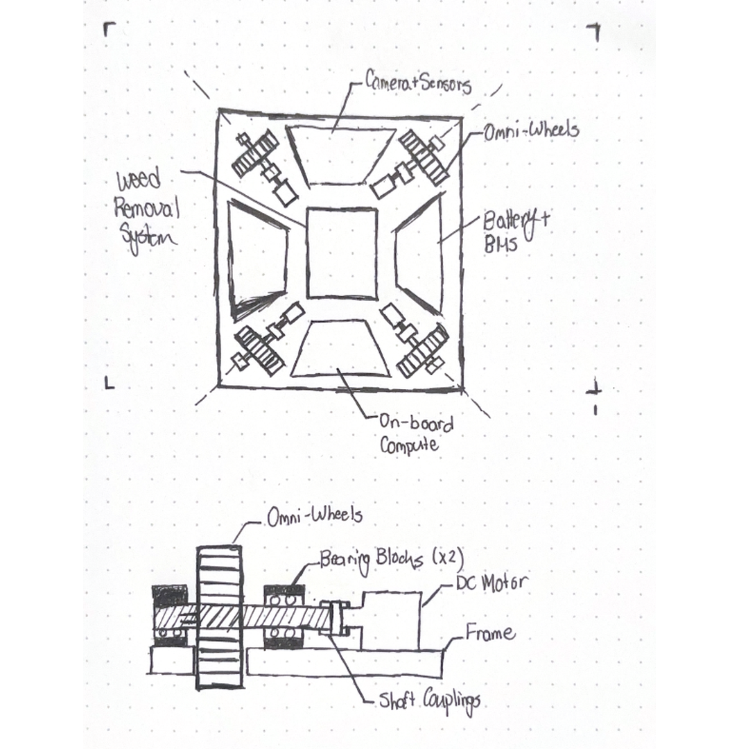
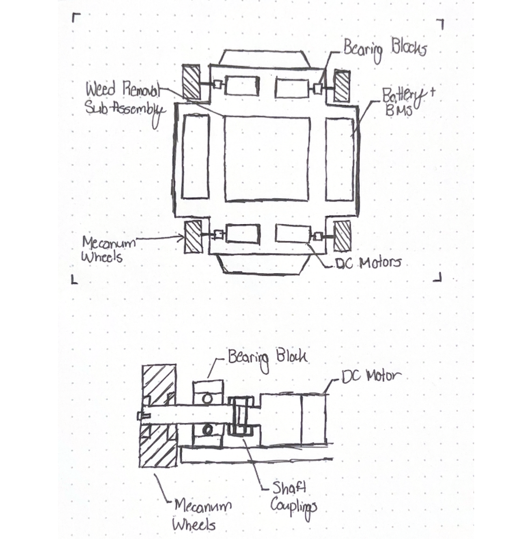
Omni-directional wheels were ruled out due to poor performance on outdoor terrain, as advised by our supervisor.
Early Software Development
While Varrun and Eric worked on concepts, I researched edge computing options for the robot:
| Option | Industry Relevance | Online Support | Dev Difficulty | Cost | Notes |
|---|---|---|---|---|---|
| Nvidia Jetson | High | Strong | Moderate | $200–$400 | Optimized for CV/ML, but older models lack support |
| Raspberry Pi | Moderate | Very Strong | Easy | $200 | Not used commercially, but easy to develop on |
| Intel Nuc | High | Strong | Easy | $300–$1000 | Not power efficient, less suited for low-level tasks |
| BeagleBone Black | Moderate | Moderate | Moderate | $100 | Better real-time performance than Pi |
I chose the Raspberry Pi 5 for its improved performance and strong community support. Nvidia Jetson Orin Nano was too expensive, and older Jetsons had poor support.
Camera
For vision, I considered only 2D image sensors to keep things simple and affordable:
| Option | Resolution | Max FPS | Pros | Cons | Cost |
|---|---|---|---|---|---|
| RPi CM3 | 12 MP | 60–120 | Official, autofocus | Limited low light, no stereo | $35 |
| Arducam IMX477 | 12.3 MP | 12–60 | Swappable lenses, high IQ | Low FPS at high res | $100 |
| Arducam IMX219 | 8 MP | 30–60 | $35 |
I picked the RPi Camera Module 3 for its autofocus and seamless RPi5 integration.
Computer Vision Pipeline
I compared classic vs. deep learning approaches:
| Approach | Pros | Cons |
|---|---|---|
| Classic | Simple, no training data, less compute | Fragile to lighting/weed variation, hard to generalize |
| Deep Learning | Robust, learns features, accurate localization | Needs training data, more compute, less interpretable |
Initially, I thought classic CV would be easier, but research showed deep learning (especially YOLO models) is now standard and accessible, even with limited data. Ultralytics’ YOLO had good RPi5 support, so I chose to start with YOLOv11n (nano), which can be exported to NCNN for edge devices.
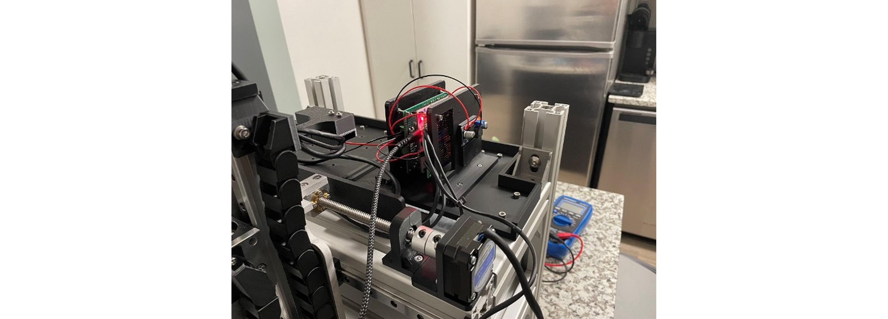
Bring Up
My first task was to get the camera and basic GPIO working on the Raspberry Pi 5.

I started with Ubuntu 22.04 for ROS2 Tier 1 support, but after three days struggling to get the camera working, I switched to Raspbian OS, which had the camera running in 10 minutes. This made ROS2 setup trickier, requiring it to run in a Docker container. Making the camera and GPIO accessible inside Docker took some effort, but once set up, I could take the RPi5 outside with a battery and use buttons to collect data.
Training the Model
Dandelion season didn’t align with our development timeline, so we bought fake dandelions for demos and rushed to collect real data before winter. I built a quick mobile setup to gather images outside.

Starting with 100 indoor images of fake dandelions, I trained a model to gauge data needs. Even with this small set, the model was impressively accurate indoors.

Confident, I collected 1400 outdoor images of dandelions and grass in local parks.

Some examples:
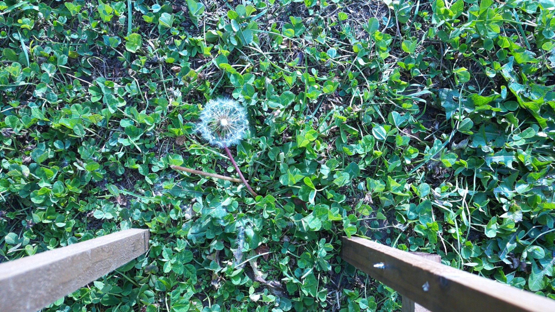
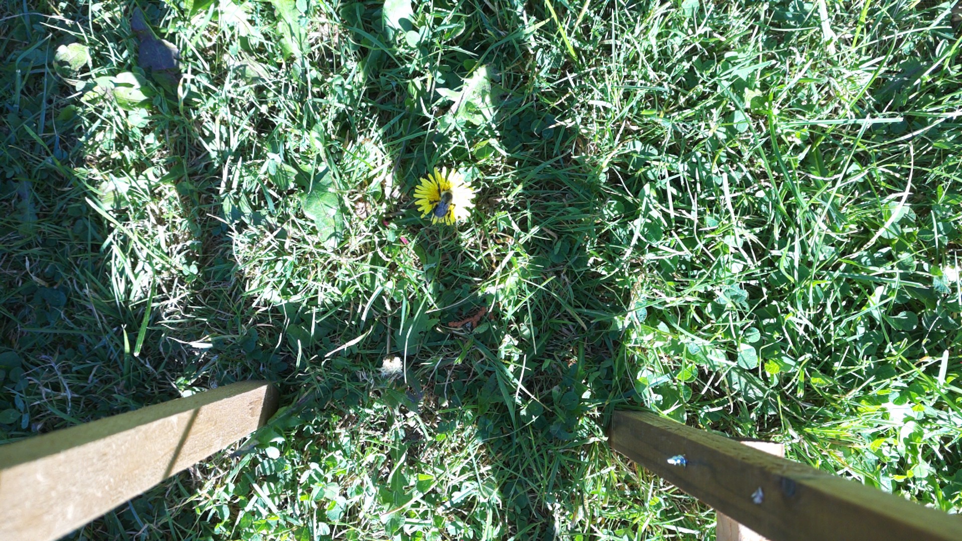
We quickly labeled 100 images using roboflow and trained a model with decent results. Since we didn’t need an outdoor model immediately, we labeled the rest gradually.

Model Type
Standard YOLO models output bounding boxes, but we needed to pinpoint the weed base. I discovered YOLO ‘Pose’ models, which predict key points in addition to boxes—perfect for our needs. My pose model included key points for the base, stem, and flower, improving localization even if parts were occluded.


The main downside: pose labeling is much more labor intensive, since each key point must be marked on every object.
Progress Report #1 - 1.5 Months In
While I was busy with the software, the rest of the team was busy working on the hardware.
Mechanical
Eric and Varrun had finished the CAD for the weed removal system and had begun fabrication.
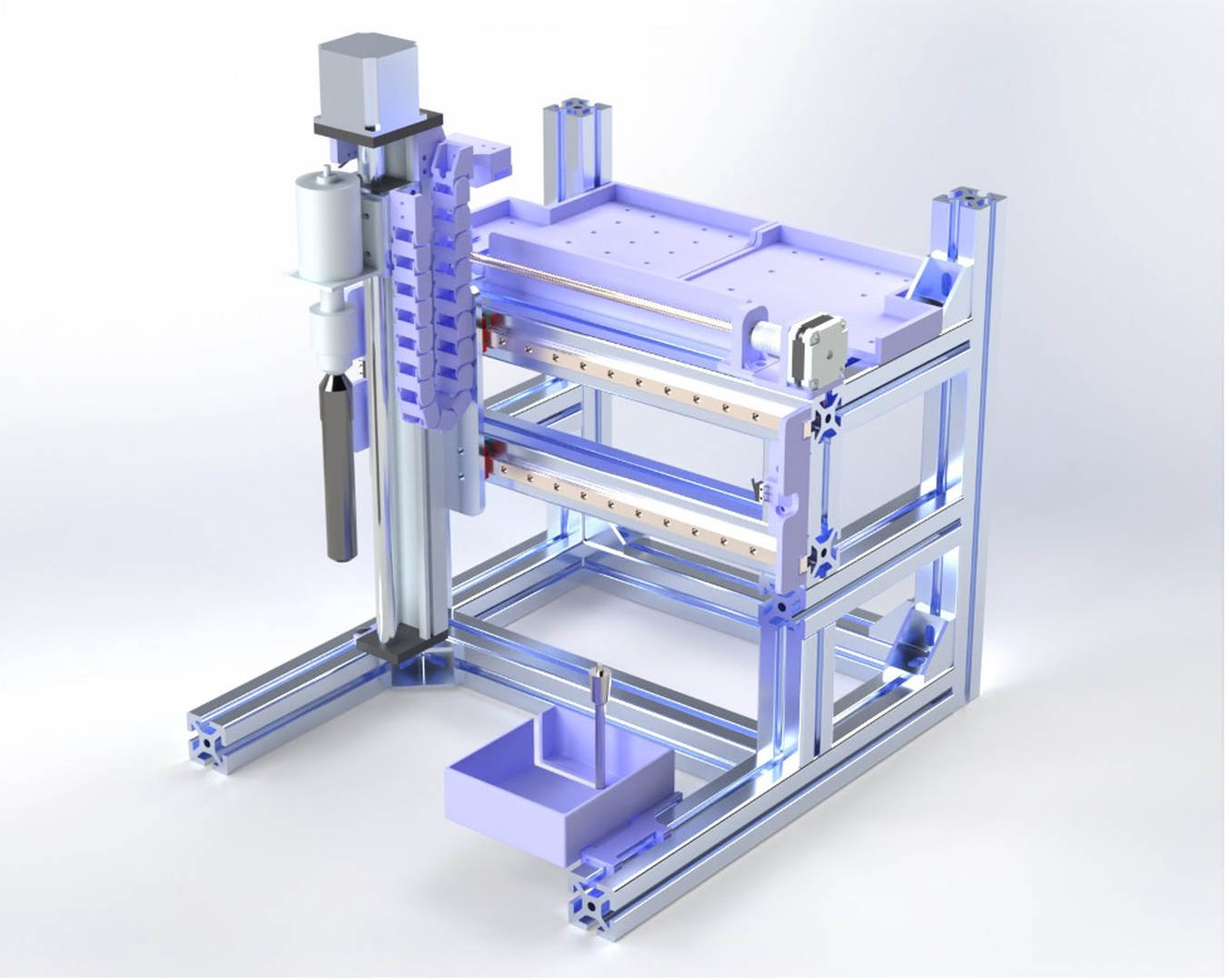
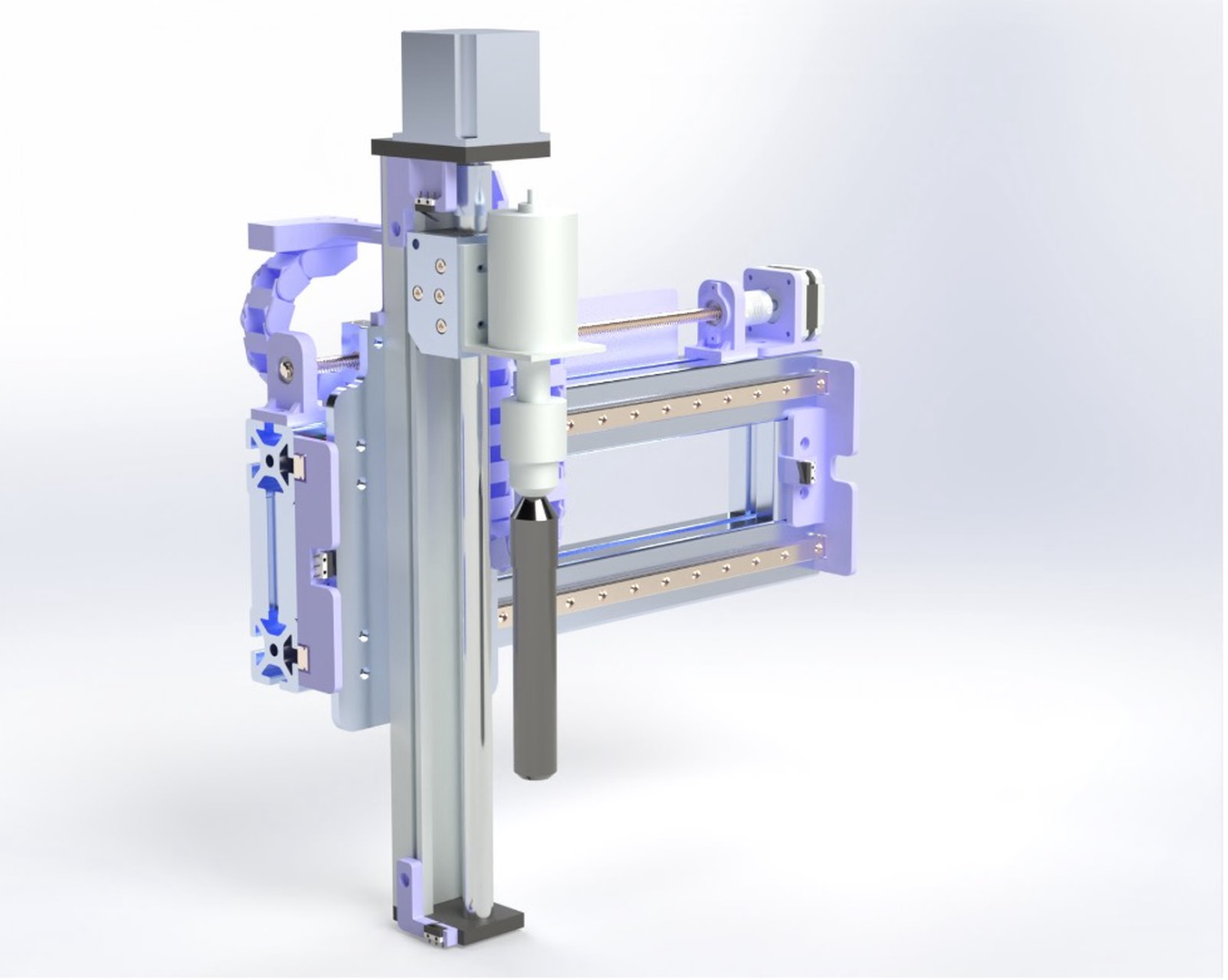
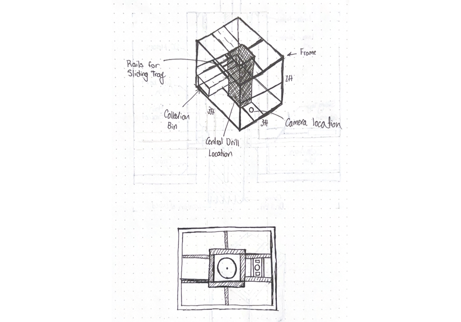
One thing to note is the bin on the bottom right of the frame. The idea was to have a spade bit mounted inside this bin and then have the coring bit spin and lower itself onto the spade bit to clear out the dirt. This was the simplest possible solution we could come up with the clear the coring bit.
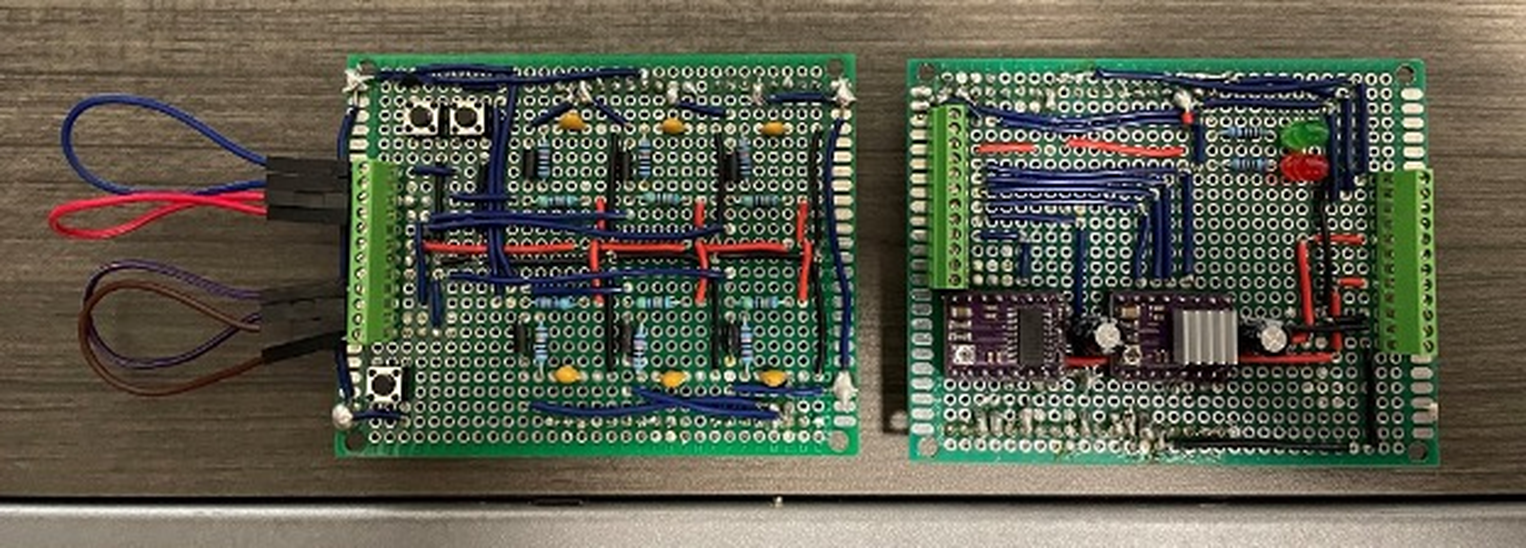
Electrical/Firmware
Ethan had been working on prototyping the electrical system for th weed removal robot, and updating the firmware from our previous project to work for this new robot.

Software Architecture
While the robot was being fabricated, I focused on developing the core software features needed to test the weed removal system: camera integration, computer vision inference, and communication with the Nucleo for cartesian axis control.

My initial ROS2 architecture was overly complex, with too many nodes running mostly sequentially, leading to unnecessary overhead. I later streamlined this for efficiency.

Despite the complexity, this setup was close to the final working system: the robot would drive, scan for dandelions, stop to localize them, position the drill, and command the Nucleo to perform removal.
Term 1 Final Design Review - 3 Months In
By this point, the electro-mechanical assembly of the removal system was complete.
The Nucleo could now control the stepper motors and position the drill along two axes with 0.1mm precision, receiving coordinates via UART from the Pi.
During the review, staff questioned the robot’s height and whether our removal method could handle a dandelion’s 12” taproot. They also suggested dropping locomotion from scope, but we decided to keep it.
Initial Design Review Term 2
Progress slowed over the winter break. Varrun added the camera and LED ring, while I sourced the locomotion electronics and developed their drivers and logic.

Motor Control
We chose high torque DC motors for their low cost, power density, and simple control. The Cytron 20A dual output driver was used.

Each motor channel uses a direction and PWM speed input. The RPi5 handles locomotion logic and control loops, but lacks hardware input capture for encoders. Therefore, the Nucleo captures encoder pulses and sends tick counts to the RPi5 for odometry, adding some UART bus complexity.
Major Autonomy Milestone #1 – Basic Demo
To make autonomy manageable, I set a clear first milestone: a simple demo where the robot would:
- Start in autonomous mode.
- Drive forward at a constant speed.
- Continuously check for dandelions.
- Stop and align its y-axis with a detected dandelion.
- Command the Nucleo to move the drill over the weed.
This guided the following architecture:

Key improvements over the previous version:
- Better use of OOP.
- Combined camera, homography, and CV model into a single class.
- Refactored UART as a reusable class.
- Simplified node logic by handling images, inference, and UART comms synchronously.
Locomotion Architecture
The locomotion system included:
- A motor control class for PWM output and safety.
- A controller node with a timer-driven control loop.
- A localization node for wheel odometry.
- A PID class for control output based on pose error.
During the demo, the decision node requested velocity from the controller. On dandelion detection, it requested a pose change along the x-axis, handled by PID control using feedback from the localization node, which updated pose estimates from encoder ticks sent by the Nucleo.
Hardware Progress
Frame Re-Design
Varrun redesigned the frame to make the robot shorter and more compact, addressing feedback that it was too tall.

The original height was due to the 10cm hole saw and spade bit for clearing debris. To simplify, we deprioritized automatic bit clearing, focusing on a more compact design and leaving advanced solutions for later.
Locomotion
Eric developed the locomotion system:

The robot uses front wheel differential drive with two passive rear wheels for stability during turns.
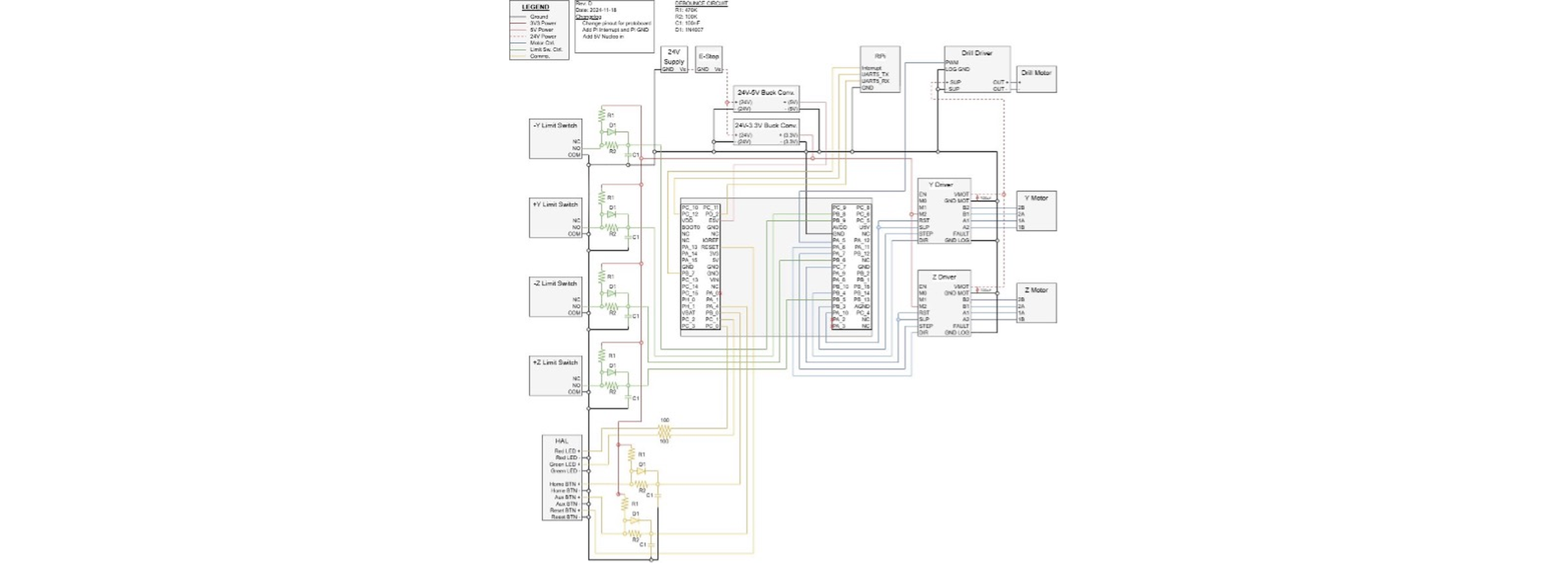
Electrical
Ethan planned the electrical layout and assembled the harnesses:

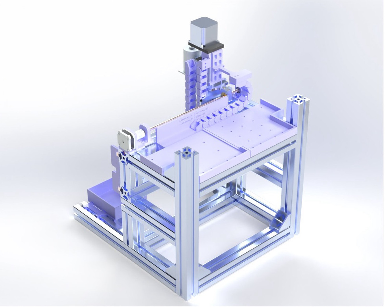
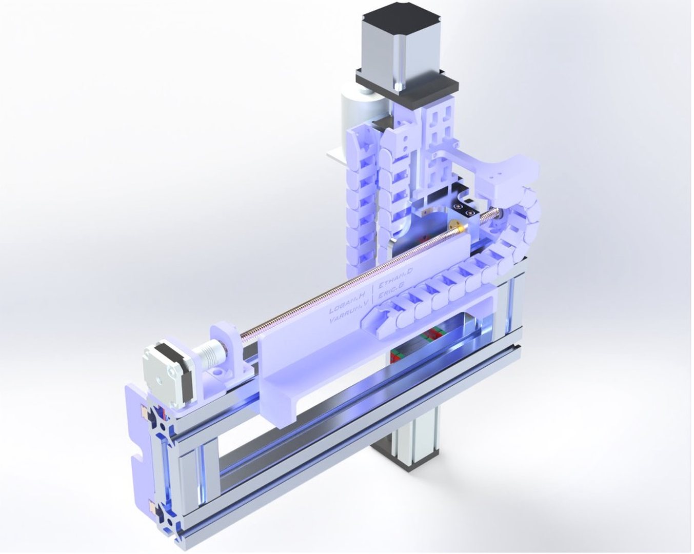
Full Assembly CAD
The complete system CAD came together quickly:

This design looked much more refined and professional, making the robot’s function clear even to non-technical viewers.

Despite its polished appearance, the design still presented many engineering challenges.
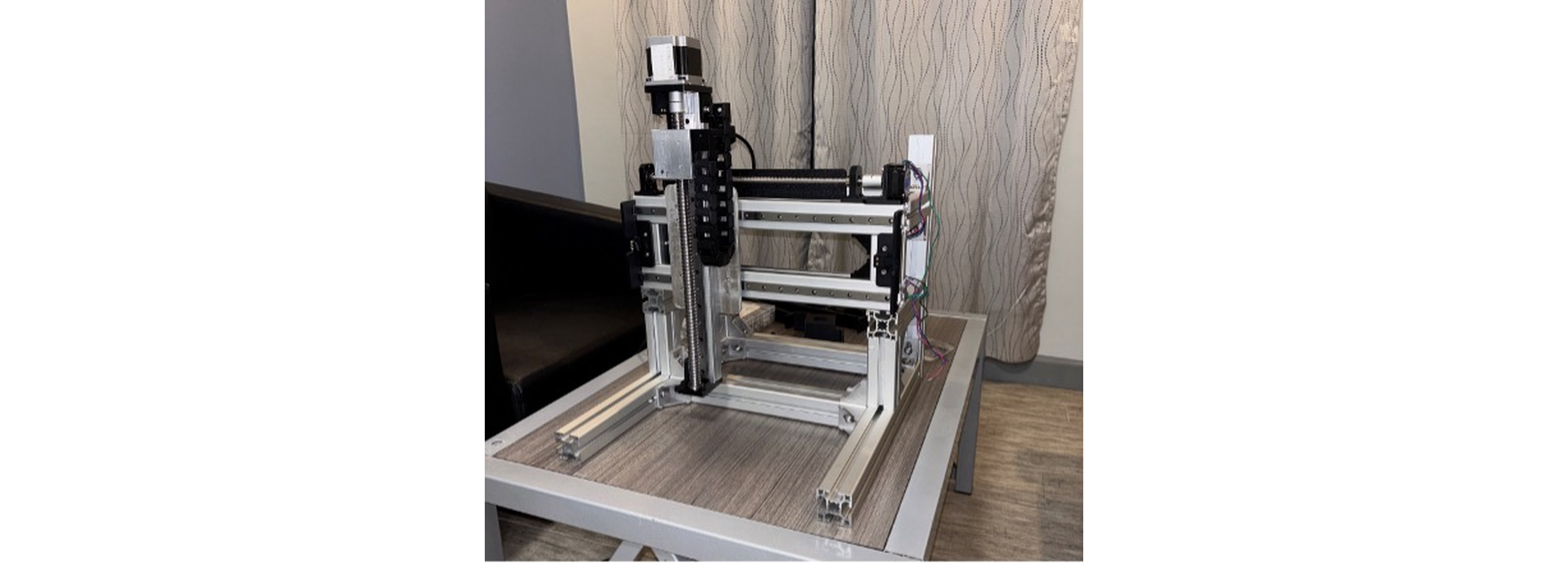
Locomotion & Weed Removal System Integration
Soon after the completion of the CAD, the new removal system was complete and the locomotion system was added.
The team was in a rush to get the system to me before they left for the long weekend, so the robot didn’t have any tires on the wheels yet.
Improving Indoor Computer Vision Performance
To boost model reliability, we needed more indoor data. Moving the system by hand was tedious, so after adding stick-on weather strips to the wheels for grip, I quickly collected 400 images of fake dandelions in various positions.

Homography Transform
After the vision model predicts a dandelion base, its pixel location must be mapped to the robot’s frame for targeting. Since the robot operates on a flat, known surface, a simple homography transform sufficed.

Using OpenCV’s findHomography, I first tried aligning a ruler to the y-axis and using points along it for calibration. This was inaccurate—errors reached 10mm.

To improve, I designed a 17-point calibration fixture. Using a laser diode on the end effector, I aligned the fixture, then used CAD for ground truth distances and OpenCV to click pixel locations.

With these 17 pairs, I used RANSAC (RANdom SAmple Consensus) to robustly compute the transformation matrix, as more than 4 points require a robust estimator. The transform matrix generated with this method, had an max error of 0.1mm across the working area.
Results
After training new models with and without the additional data and applying the improved homography transform, we evaluated each model on 5 images across 5 dandelion configurations, measuring true base positions.
| Model Description | Dist. (mm) | Point Conf. | Box Conf. | Point Type | Num. Boxes |
|---|---|---|---|---|---|
| Original indoor pose model | 92.52 | 0.90 | 0.67 | 1.03 | 2.20 |
| Only new indoor data | 10.01 | 0.95 | 0.72 | 0.83 | 1.20 |
| All indoor data | 8.27 | 0.93 | 0.78 | 0.50 | 1.03 |
| Old indoor model retrained on new data | 11.23 | 0.95 | 0.71 | 0.97 | 1.20 |
The best model achieved 10x better base localization accuracy, more consistent base key point predictions, and fewer false positives compared to the initial model. Our goal was to be able to target dandelion bases with greater than 12.5mm accuracy, and given that our cartesian system was accurate to 0.1mm, this was promising.
Midterm Design Review - 5.5 Months In
Leading up to the midterm design review, we addressed several reliability issues with the locomotion system—bolts, couplers, and grub screws kept coming loose, causing slack and shaft slipping. Fully resolving these took most of the term. On the software side, odometry accuracy was a challenge due to an incorrect stated gear ratio, which I determined empirically. There were also data typing issues in Pi–Nucleo communication.
With locomotion mostly stable, I integrated all parallel software features into “autonomous mode” the night before the review. Despite some integration hiccups, I achieved a working milestone by midnight.
Feedback
During our design review, the teaching team doubted our drivetrain. They pointed out that grub screws weren’t reliable for securing the drive wheels (they were right) and that two fixed passive rear wheels would hinder turning (also correct). We were initially defensive, expecting higher torque motors to solve our issues—but we were wrong.
Side Note: I accidentally ordered 230RPM motors instead of 23RPM, so the robot moved too fast with little torque. With the correct 23RPM motors, we hoped for better turning, but the drivetrain design was still a problem.
One comment that stood out was, “make sure you don’t oversell what you’ve got here.” I was frustrated, feeling we had achieved a lot in a short time, but in hindsight, the advice was partly justified, even if poorly delivered.
Re-Branding
The feedback about “overselling” stemmed from our focus on autonomous mobility rather than fully eradicating weeds. Dandelions regrow from deep taproots, which our design didn’t address. After discussion, we shifted from “weed removal” to “weed control.”

Instead of removing weeds, our robot would blend up the visible parts nightly using a bit like the one above, suppressing regrowth by depriving the plant of light. This approach is used by other products and supported by research.
Re-Design of the Locomotion System
Initially, the team was hesitant to redesign the drivetrain before testing the new high-torque motors. However, I suspected the slippery TPU wheels and dual passive wheels would still cause traction and friction issues, especially given the robot’s weight. To demonstrate this, I ran my own tests.
caster Wheel Testing
I attached a caster wheel from Home Depot to the back of the robot and compared its maneuverability to the original setup by driving in an arc. The videos below show the dramatic improvement:
The caster made turning much easier, proving the need for a new drivetrain. This convinced the team to move forward with a redesign.
Finally, some fun driving.
Developing New Tires
Since making custom rubber tires seemed daunting, I experimented with silicone, which was readily available.
Key challenges in designing the 3D printed mold included:
- Optimizing air hole density and size
- Finding an effective mold release agent
- Deciding how much to undersize the tire for a snug fit
Stretching the soft silicone helped stiffen the tires.

After successful small-scale tests, I made a full-sized version—the improvement in traction was immediate.
Watching the video, you can see the right side of the robot jerks more aggressively as the tire maintains traction while the TPU tire slips out.
Drivetrain Testing
To choose the best drivetrain, we tested four passive wheel setups:
- Original dual fixed wheels
- Wide dual fixed wheels (less friction)
- Single caster wheel
- Dual caster wheels
We ran these tests:
- Zero point turn: Opposite drive wheels, measure rotation/displacement.
- Arc turn: Drive in an arc, measure deviation.
- Side hilling: Max slope before sliding.
- Tipping point: Force at which wheels lift during drilling.
- Circuit test: Timed course, note handling.
Zero Point Turn – Single Caster
Arc Turn – Dual Caster
Tipping Point – Thin Passive Wheels (Original)
Circuit Test – Thin Passive Wheels (Original)
Circuit Test – Single Caster Wheel
Summary:
- Casters outperformed passive wheels in all driving tests.
- Single caster was more agile but slightly less stable than 4-wheel setups.
- Casters struggled with side hilling.
- Single caster was more maneuverable than dual caster.
We prioritized maneuverability over maximum stability, choosing the single caster. In hindsight, consulting mobile robot research and kinematic models could have saved time.
Path Following
With the locomotion system functional, I implemented path following using a list of waypoints, each with global coordinates and a point type to adapt PID control for different maneuvers (e.g., higher angular gain for turns). However, localization was poor.
In the video above, the robot should trace the turf’s edge and return, but it drifts off course. Main issues:
- Wheel slip, especially during turns (TPU tires, aggressive speed ramp).
- Poor orientation estimation due to drive system slack—turns were inaccurate, and slack would slip out during forward motion.
Improving controls and switching to silicone tires greatly improved odometry-based path following.
Despite this, orientation errors persisted.
Extended Kalman Filter (EKF)
To address heading drift, I implemented an EKF fusing wheel odometry with the BNO085 IMU, which provides robust, drift-compensated orientation via onboard sensor fusion.
The EKF state-space model is shown below:


The process covariance matrix P adapts to motion and measurement confidence. BNO085 outputs were transformed to the robot’s frame before fusion. Including the BNO085’s fused orientation in the EKF measurement model significantly improved heading accuracy, especially during slip or sparse encoder updates.
To tune the Q and R matrices, I collected 10 datasets over 5 paths, capturing ground truth with OptiTrack. Offline optimization (BFGS) minimized mean squared error between estimated and ground truth paths. A second round of data collection and tuning further improved localization, yielding strong demo performance.
In the video, you can see the robot correcting the orientation error on the straight sections of the path. With the EKF, the robot was able to nearly perfectly trace the turf.
Updated Software Architecture
With new features came updates to the software architecture.

Key changes:
- UART: Now its own node, handling messages from multiple sources. Nucleo sends encoder ticks every 50ms via hardware timer.
- Localization: Odometry and BNO085 are separate nodes. Odometry updates on encoder tick reception; BNO085 polled every 50ms. ROS2 fused callback combines both in the EKF, posting pose updates for the controller.
- Path Planning: The decision node receives paths from a planner. The controller signals the decision node after each segment, keeping behaviors in sync.
Final Design Review – 7 Months In
For the final review, I integrated weed removal logic with path following to demonstrate autonomy. The resulting videos (also shown at the top):
The teaching staff was highly impressed, calling it one of the best capstone projects they’d seen.
Symposium Preparation
To ensure robust live demos at symposium, I refined edge-case behaviors. For example, if the robot stopped too late and missed a dandelion, it would roll back 10cm to double-check.
Outdoor Model Demo
To show real-world viability, we labeled all outdoor images and created an interactive demo for the symposium.
Visitors could run live inferences with our outdoor detection model.
Poster
My sister Leandra designed our symposium poster.

Symposium Day
The days before symposium were relaxed—we were well prepared.
We ran live demos:
A monitor displayed the latest computer vision inference so visitors could see real-time detection.

Feedback was overwhelmingly positive—many said it was among the best projects they’d seen, especially with live demos.
Reflection
This is by far the largest project, both in scope and time commitment that I’ve ever completed. I’m extremely impressed and satisfied with what we accomplished over our final year of university. I think we did an excellent job of showcasing our technical skills.
A lesson that this project taught me was the value of viewing the development through the lense of a product, in this case, a consumer product. We had set out to make something that could have market value, but we didn’t want to fixate on it or take it too seriously. I think this was a major mistake. I think had we been more critical of our design decisions from the lens, we would have spotted flaws in our approach much sooner and could have made and even more impressive robot.
I were to design this robot again, I would make it much smaller and more light weight. The robot’s original footprint was in part driven by the need to counteract the upward forces generated when extracting a weed. But if we were only blending up the weeds, a much smaller, more agile and more efficient robot could have been possible.