EE/Hardware Design
ByLinear Regulators
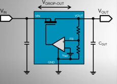
Maintains a stable output voltage, even when the input voltage is slightly higher or lower, by minimizing the voltage dropout between the input and output.
Interview Questions
- Dropout voltage refers to the minimum voltage difference required between the input and output of an LDO regulator for it to maintain regulation.
- LDOs achieve low dropout voltage by utilizing a low resistance pass transistor, which minimizes the voltage drop between the input and output.
- The current at the input of an LDO is typically higher than the current at the output due to additional internal losses and current consumption.
1st Principles
- LDO: The device contains a MOSFET and an error amplifier. The output of the amp is used to control the conductivity of the MOSFET. Resistance across the MOSFET results in a voltage drop. The MOSFET dissipates power as heat. Can regulate voltage even when input is close to output.
Switching Regulators
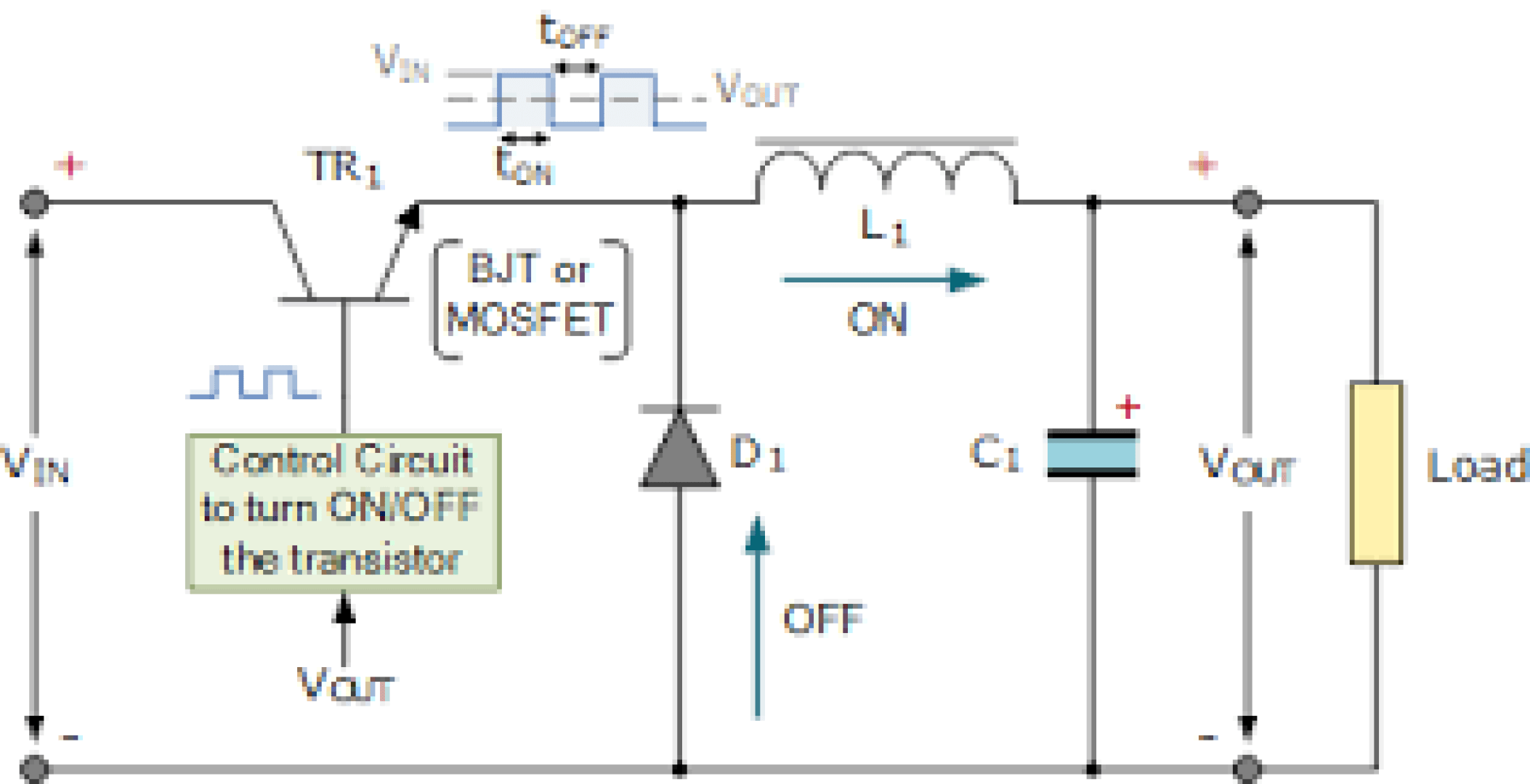
A switching power supply is an electronic device that converts and regulates electrical power by rapidly switching the input voltage on and off to achieve efficient power conversion.
Interview Questions
- A linear power supply uses a series pass element to regulate the output voltage, dissipating excess energy as heat, whereas a switching power supply uses high frequency switching to regulate and convert the input voltage to the desired output voltage with higher efficiency.
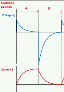
- A flyback converter is a type of switching power supply that stores energy in an inductor during the “on” time of the switch and releases it to the output during the “off” time, providing voltage transformation and isolation.
- The main components of a switching power supply include a power switch (such as a MOSFET), an inductor, a diode, a capacitor, and a feedback control circuit.
1st Principles
- Switchers: Control circuit sends a PWM signal generated from an error amplifier and an oscillator which controls the conductivity of the control element (FET).
- Stepdown: When the control unit is on, the inductor charges up, and the load and filter are supplied with current. When turned off, the inductor releases energy directed by the diode into the filter (cap)
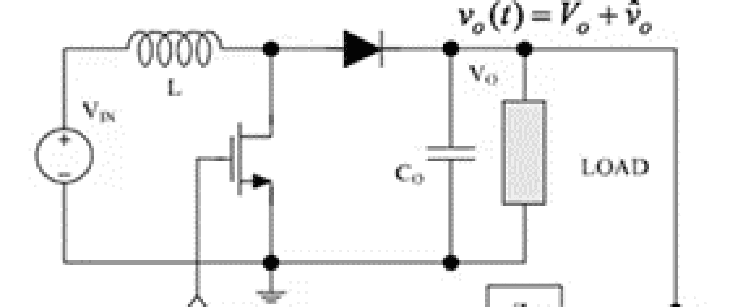
- Step-up: When the control unit is on, the inductor charges up and the load is supplied by the filter through the diode. When the unit is off, the energy in the inductor is added to input voltage and the inductor supplies the load current and restores charge on the filter.
Semiconductors
A substance with neutral conductivity that can be doped to behave as a conductors or insulator under certain conditions
1st Principles
- Silicon does not contain free electrons.
- N-type: silicon that is doped with phosphorus which adds free electrons which will flow towards a positive voltage.
- P-type: silicon that is doped with boron adds holes which will flow towards negative voltage and pull electrons to fill their places.
Diodes
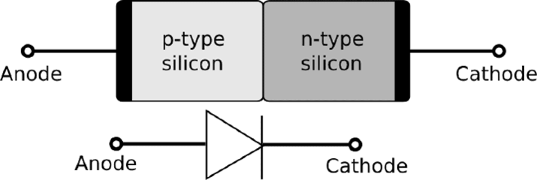
A diode is a two-lead semiconductor device that acts aa a one-way gate to electric current. 1st Principles
- Forward biasing:
Vanode > Vcathode - p-n junction diode: n-type at cathode, p-type at anode. When forward biases, holes and electrons move towards p-n junction and current flows. Reverse bias -> move away.
- Takes a minimum voltage to turn it on
Where I’ve used them
- Schottky: asynchronous buck converters, reverse polarity circuits
- Zener: voltage regulation/protection, current sense output
Interview Questions
- A rectifier is a specific type of diode designed for converting alternating current (AC) to direct current (DC) by rectifying the waveform.
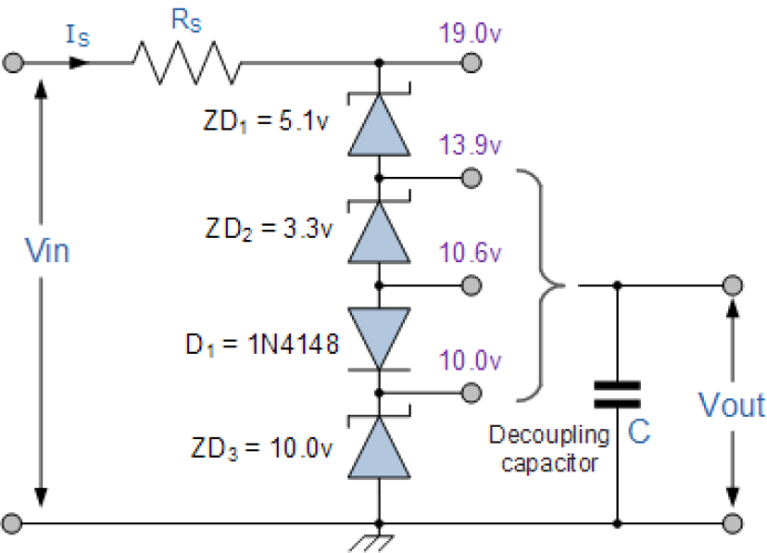
- A Zener diode is specifically designed to operate in the reverse breakdown region, maintaining a constant voltage across it when the reverse voltage exceeds its breakdown voltage.
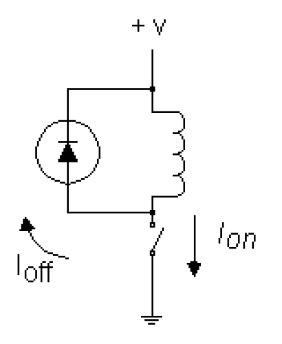
- A flyback diode is used to provide a path for the current when an inductive load, such as a relay or motor, is switched off, preventing voltage spikes and protecting other components.
Applications
- Schottky: Known for low junction capacitance, faster switching speed, and lower voltage drop. Commonly used in DC/DC converters, protection circuits.
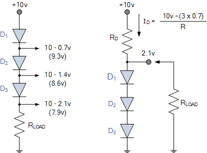
- Voltage Dropper/Regulator:
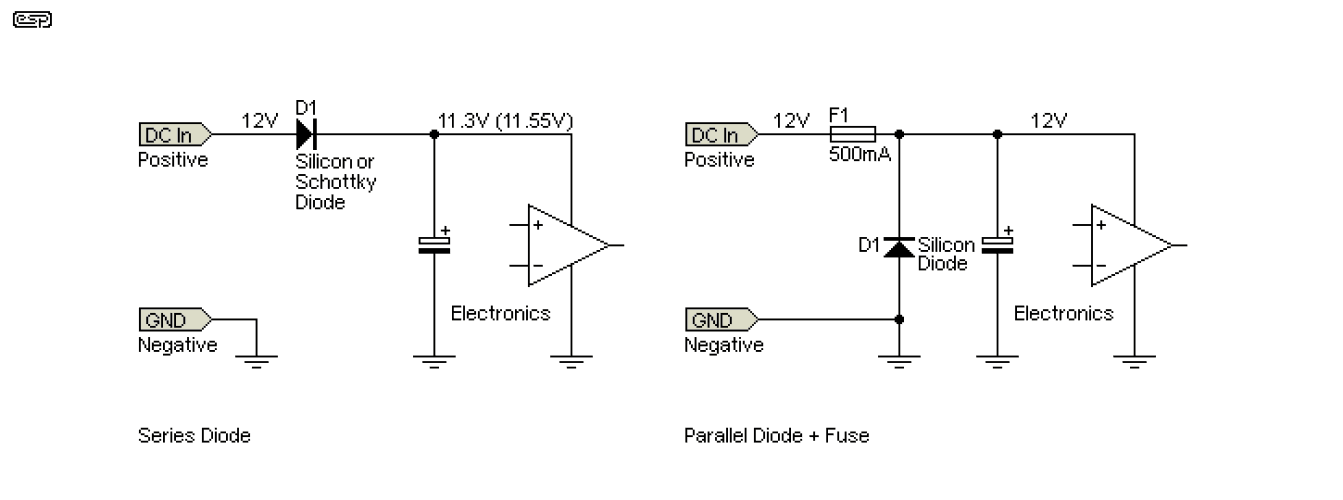
- Polarity Protection:
- Inductive Kick Protection:
- Zener Voltage Regulator:
Transistors
Transistors are semiconductor devices that act as either electrically controlled switches or amplifier controls.
Application
- pnp: normally off,
Vb < Ve -> ON.Vc > Ve. - npn: normally off,
Vb > Ve -> ON.Vc < Ve. - J/D-nch: normally on,
Vg < Vs -> OFF. - J/D-pch: normally on,
Vg > Vs -> OFF. - E-nch: normally off,
Vg > Vs -> ON. - E-pch: normally off,
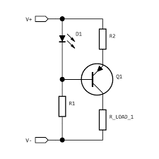
Vg < Vs -> ON. - Current source:
Interview Questions
- BJT vs FET: BJT require input current at their control leads whereas FETs require only voltage. Input impedance of FET is much higher.
- Enhancement vs Depletions: Depletion is normally on; enhancement is normally off.
- Ohmic region: Acts like a variable resistor.
- Saturation/Active region: Resistance level is most influenced by gate voltage.
- Cut off voltage: JFET acts like an open circuit.
- Breakdown voltage: Vds is large enough to breakthrough.
1st Principles
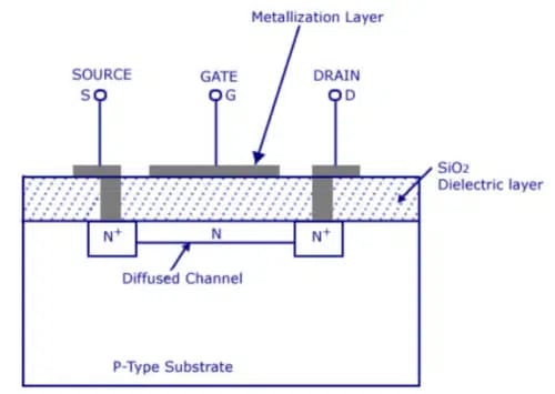
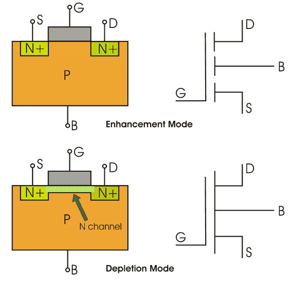
- MOSFET (nch-depletion):
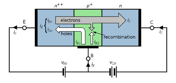
- Bipolar (npn): Collector(n), base(p), emitter(n). When a positive voltage is applied to the base, the p-n junction between the base and emitter is forward biased. The electrons are pulled toward the base but also jump across the emitter junction since it is so thin. Increasing the base voltage increases the jumping effect -> amplification?
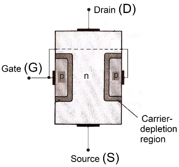
- JFET (nch): n-type channel with two p-type bumps attached to the gate. When no voltage is applied, current can flow freely through the n-channel. When a negative voltage is applied to the gate, a depletion region is created in the channel that makes it harder for the electrons to flow.
- MOSFET (nch): Depletion works like JFET above but with a different physical layout (below). For enhancement, the channel is normally resistive. When a positive voltage is applied to the gate, electrons in the p-type move towards the channel region and increase the conductance of the channel.
OpAmps
An operational amplifier (op amp) is an electronic device that amplifies and processes analog signals.
1st Principles
- High input impedance
- Low output impedance
- High-gain differential amplifier
Applications
- Comparator
- Instrumentation Amplifiers
- Buffered inputs
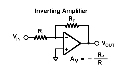
- Inverting amplifier
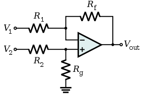
- Difference amplifier
Where I’ve Used Them
- Current sensing for the power distribution board
Interview Question Answers
- Ideal op amps have infinite input impedance and gain, 0 output impedance.
- Inverting configuration connects to the negative terminal, output is inverted.
- Negative feedback stabilizes and controls the gain of the op amp, improves linearity. Formula:
-Rf/Ri. - Op amp comparator compares the input voltage with a reference voltage and produces a digital output.
- Slew rate is the maximum rate at which the output voltage of an op amp can change.
Resistors
A resistor is an electrical component that opposes the flow of current, dissipating electrical energy in the form of heat.
Interview Questions
- The resistance value of a resistor is determined by its physical characteristics, such as the length, cross-sectional area, and resistivity of the material used.
- The resistance of a resistor increases as its temperature increases, due to the increased collisions between electrons and atoms within the material.
- The power rating of a resistor indicates the maximum amount of power it can safely dissipate without overheating.
1st Principles
- As an electron moves through a conductor, it undergoes collisions with other electrons, lattice ions, and impurities within the lattice, which limits the electron’s forward motion. This is what produces electrical resistance.
- The collisions that occur within a conductor produce heat. The more resistive a conductor is, the more heat it will dissipate for a given current.
- Increasing the length of a conductor increases resistance, while increasing the cross-sectional area decreases it. Electrons confined to a smaller volume will collide more often.
- Resistivity is a material property that characterizes a material’s ability to conduct electricity.
Capacitors
A capacitor stores and releases electrical energy, acting as a temporary reservoir for charge in an electrical circuit.
Interview Questions
- Capacitance is proportional to the surface area of the plates, the distance between the plates, and the type of dielectric material used.
- The voltage rating indicates the maximum voltage that a capacitor can withstand before it will experience dielectric breakdown.
- Capacitance reactance refers to the resistance of a capacitor to changes in voltage or alternating current. It is inversely proportional to the frequency of the alternating current signal, and its value decreases as the frequency increases.
- ESR in a capacitor represents the internal resistance of the capacitor. It affects the capacitor’s ability to deliver current.
- Dielectric breakdown occurs when the voltage across the capacitor plates is large enough to create an electric field strong enough to break down the dielectric material.
1st Principles
- Composed of two oppositely charged parallel conducting plates separated by a small distance. Applying a voltage across the plates causes electrons to collect on the negative plate and depart from the positive plate. Once the plates are charging, an electric field is generated between the plates.
Inductors
An inductor stores energy in the form of a magnetic field when current flows through it. It consists of a coil of wire wound around a core.
Interview Questions
- Inductance is determined by the number of turns in the coil, the coil’s geometry, the core material, and the presence of any magnetic shielding.
- Inductive reactance refers to the opposition of an inductor to changes in current flow. It is directly proportional to the frequency of the alternating current signal and its value increases as the frequency increases.
- Saturation current is the maximum current that an inductor can handle before its core saturates. When the core saturates, the inductance value decreases significantly.
- The Q factor represents the efficiency of an inductor and is a measure of how well the inductor stores energy and minimizes losses.
1st Principles
- Moving electric currents generate magnetic fields. Inductors are constructed from loops of conductor, so that when current passes through the loops, the magnetic fields generated by the moving electrons sum up.
DC Motors
Features
- Can reverse the direction of the motors by changing the voltage polarity of the terminals.
- Operates most efficiently at rated voltage.
- 3000-8000 rpm
- Speed control is done most efficiently with PWM.
Speed Control
- A DC motor’s speed can be controlled by limiting the current to the motor with a potentiometer, however, this requires the pot to dissipate a lot of heat.
- A better approach is to use PWM: By sending short pulses of current and varying the width and frequency of the pulses, the speed can be controlled.
RC Servos
Remote control servos are motor-like devices designed specifically for position control applications.
Features
- Limited range (180-210 degrees) due to the potentiometer.
- Provides low-speed torque.
How it Works
- Uses an external PWM signal to control the position of its shaft within a small fraction of its maximum range.
- A potentiometer is coupled to the servo shaft which provides position feedback to the control circuit.
- The control circuit uses this resistance along with the PWM input to drive the motor a specific number of degrees then hold.
Stepper Motors
Steppers are digitally controlled brushless motors that rotate a specific number of degrees every time a clock pulse is applied to a special translator circuit used to control the stepper.
Features
- Position control.
- Continuous rotation.
- High precision.
- High torque at low speeds.
- Requires a controller in order to drive.
How it Works
- Stepper motors operate based on the interaction between electromagnetism and magnetic fields. It uses multiple coils energized in a specific sequence to create a magnetic field that interacts with permanent magnets, causing the rotor to move in discrete steps.
Motor Interview Questions
- Electric motors work by the interaction of magnetic fields generated by electric currents in the motor’s coils and permanent magnets, causing a rotational force known as torque.
- AC motors operate on alternating current and commonly use induction or synchronous principles. DC motors operate on direct current and often utilize brushed or brushless designs.
- Commutation is the process of switching the direction of current flow in the motor’s coils to ensure continuous rotation. It is crucial for the motor’s operation.
- Brushed DC motors use brushes and a commutator to switch the current direction in the motor coils, while brushless DC motors use electronic commutation without brushes.
- The speed and torque of a motor depend on factors such as the applied voltage, current, the motor’s design, the number of windings turns, and the load on the motor.
- Motor efficiency is a measure of how effectively a motor converts electrical energy into mechanical energy.
Microcontrollers
A computer on a chip.
Interview Questions
- A microcontroller is a complete system with integrated memory, peripherals, and I/O ports, whereas a microprocessor is only a processing unit and requires external components for operation.
- GPIO pins on a microcontroller provide digital I/O functionality.
- Interrupts are signals that temporarily halt the normal execution of a program to handle specific events or external signals.
- RAM (Random Access Memory) is volatile memory used for temporary data storage and program execution, while ROM (Read-Only Memory) stores permanent data or program instructions that are not modified during normal operation.
- A watchdog timer is a built-in hardware timer in a microcontroller that triggers a system reset if it is not periodically reset by the software.
- A bootloader is a program that resides in the microcontroller’s memory and allows the user to update or replace the firmware or program code without the need for external programming hardware.
- Timers in microcontrollers are used for tasks such as generating accurate time delays, measuring the duration of events, generating PWM signals, and controlling timing-critical operations.
How Does It Work?
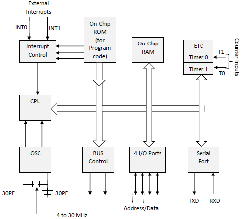
- The basic ingredients of a microcontroller are CPU, ROM, RAM, I/O ports, timing circuitry, interrupt control, serial port adapters, and ADC/DAC.
- The CPU retrieves the program from the ROM while using the RAM for data during execution. I/O ports can send and receive data from external elements.
- Serial port adapters facilitate serial communication between devices.
- The interrupt system can halt program execution to run an interrupt service routine.
- A timer/counter is used to clock the device and is the driving force for moving bits around.
- ADCs and DACs allow for reading and generating analog signals.
SPI (Serial Peripheral Interface)
SPI is a synchronous serial communication protocol, utilizing a master-slave architecture with separate data lines for transmission and reception.
Benefits
- Higher Speed.
- Simpler protocol with fewer overheads.
- Often directly integrated into microcontrollers or peripheral devices, reducing the need for external components.
- Operates in a point-to-point fashion, where each slave device has a dedicated chip select line, providing better control and isolation of devices on the bus.
Interview Questions
- The chip select line is used to select a specific slave device on the SPI bus.
- Clock polarity defines the idle state of the clock (high or low), while clock phase determines when data is sampled or latched.
I2C (Inter-Integrated Circuit)
I2C is a synchronous serial communication protocol that enables data exchange between integrated circuits using a shared bus, allowing multiple devices to be connected and controlled by a master device.
Benefits
- Fewer signal lines.
- Supports multiple master devices on the bus.
- Utilizes addressing mechanisms, enabling communication with a large number of devices connected to the same bus.
- Generally consumes less power compared to SPI due to its simpler structure and lower clock rates.
Interview Questions
- The Start condition indicates the beginning of a data transfer, where the master pulls the SDA line low while the SCL line is high. The Stop condition marks the end of the transfer, with the master releasing the SDA line from low to high while the SCL line is high.
- Clock stretching is a feature in I2C where a slave device can hold the clock line (SCL) low to pause the data transfer until it is ready to proceed, allowing slaves to control the data rate and synchronize with their processing capabilities.
- In I2C multi-master communication, if two or more masters attempt to access the bus simultaneously, arbitration occurs. The master that pulls the SDA line low and wins arbitration continues its communication, while the other masters release the bus and retry later.
PCB Design and Manufacturing Notes
The Process
- Designing the PCB layout using computer-aided design (CAD) software.
- Generating Gerber files or other manufacturing data formats from the PCB design.
- Preparing the raw materials:
- Selecting the appropriate substrate material, usually fiberglass-reinforced epoxy resin (FR-4).
- Cleaning and preparing the copper-clad laminate.
- Applying a photosensitive film called photoresist to the copper surface.
- Transferring the Gerber files onto the photoresist using a process called photolithography:
- Exposing the photoresist to UV light through a photomask, creating a pattern.
- Developing the photoresist to remove the unexposed areas, leaving the patterned resist.
- Etching the exposed copper using a chemical solution:
- The photoresist protects the desired copper traces while the exposed copper is dissolved away.
- Removing the remaining photoresist to reveal the copper traces.
- Drilling holes for component mounting and through-hole vias.
- Electroplating the walls of the holes with a conductive material to create plated through-holes.
- Applying a protective solder mask to cover the copper traces, leaving only the desired areas exposed for soldering.
- Applying a silkscreen layer for component markings and reference designators.
- Surface finishing:
- Options include HASL, ENIG, OSP, and others.
- Testing the completed PCB for continuity, shorts, and other potential defects.
- Separating the individual PCBs from the manufacturing panel (depanelization).
- Inspecting and quality control checks.
- Packaging and shipping the finished PCBs.
Design Interview Questions
- A ground plane provides a low impedance path for return currents, helps with shielding, reduces noise, and improves signal integrity in high-speed circuits.
- Through-hole vs Surface-mount components: Through-hole offers better mechanical strength but is bulkier and more time-consuming to assemble. Surface-mount components are smaller, easier to automate, and enable higher densities.
- Vias are conductive holes that connect traces between different layers of a PCB.
- High-speed PCB designs: Techniques include proper trace routing, minimizing signal reflections, reducing crosstalk, using termination techniques, and managing power and ground planes.
- DFM (Design for Manufacturability): Designing a PCB to maximize ease and efficiency of manufacturing processes.
Manufacturing Interview Questions
- The solder mask is a protective layer applied to the PCB to prevent solder bridging between traces during assembly.
- Main steps in PCB manufacturing include design layout, creating manufacturing data, preparing materials, applying photoresist, etching, drilling, plating, solder mask application, silkscreen printing, surface finishing, testing, and final inspection.
- Common surface finishes include HASL, ENIG, OSP, and immersion tin or silver.
- Automated optical inspection (AOI) inspects PCBs for defects such as missing components, misalignments, and soldering issues.
- Vias creation involves drilling holes in the PCB and electroplating them with a conductive material to establish connections between layers.
Load Cell and Wheatstone Bridge Fundamentals
Strain Gauge
- An electrical sensor that measures strain caused by stress.
- Consists of a resistive element, such as a wire bonded to a material.
- As the material deforms, the length and cross-section of the resistive element changes, resulting in a change in resistance.
- The change in resistance is used to infer a change in force.
Wheatstone Bridge
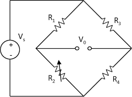
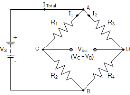
- A typical method for accurately measuring small voltages is to use a Wheatstone bridge.
- Consists of two voltage dividers wired in parallel with a common voltage source.
- The supply voltage (Vs) is a constant DC.
- The output voltage is measured at Vo.
- If all the resistances are equal, Vo will be zero.
- If one changes, Vo will change.
Load Cell
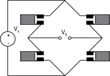
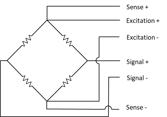
- A load cell consists of strain gauges in a Wheatstone configuration.
- A load cell with four strain gauges is most common and is called a full bridge.
Load Cell Signal Output
- If a load cell output is 2mV/V and the supply voltage (excitation voltage) is 5V, then at its maximum rated load, Vo will be 10 mV.
- If the load cell is compression or tension only, the range may be 0-10 mV.
- If it works in both, then the range would be -10 mV to 10 mV.
- Increasing excitation voltage can increase the signal-to-noise ratio, as long as the maximum expected output of the load cell does not exceed the limits of the ADC input.
Wire Sense for Load Cells
- Achieving accurate measurements from a load cell requires knowing the precise voltage that is being applied to the load cell.
- The resistance in the supply and return wires will reduce the voltage. This effect can be significant for long wire runs.
- Thus, many load cells add two remote sensing wires so the controller can measure the voltage that is actually being applied at the load cell, providing more accurate measurement.
What is a Full Bridge Bridge
- A bridge is an electrical circuit that connects two nodes by means of a path between them.
- Most common is the Wheatstone bridge:
- Most common is the Wheatstone bridge:
Bridge Converter
- An electrical circuit that changes DC to AC or vice versa.
Half Bridge vs Full Bridge
- A half-bridge converter is a variant of a bridge converter that uses two switches rather than four diodes.
- A full-bridge converter is a type of bridge converter that uses four switches instead of two.
Half Bridge Advantages
- Less EMI.
- No gaps on magnetic path.
- Small magnetic cores required.
Half Bridge Disadvantages
- Operates at half the supply voltage.
- Not compatible with current mode control.
Advantages of Full Bridge
- More efficient.
- Operates at full supply voltage.
Disadvantages of Full Bridge
- More expensive.
- Harder to use.
- Noisy.
