SCARA Robot
Design Challenge
This project was completed as part of a design project course at the University of Waterloo.
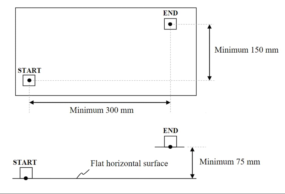
The challenge was to design an electro-mechanical system that could move a 50x50mm, solid PLA, 20-sided die from a start location to an end location with a delta of 300x150x75mm from the start location. Additionally, the final design could not cost more than $300 and could not make use of projectile motion.
Each team also had to pick two additional design objectives that they would have to prove their design meets. Our group chose repeatability and accuracy as our additional design objectives.
The final design had to be complete within 3 months and ready for an in person functional demo, where the design would be scored by the teaching team judges.
The Team
The project was to be completed in groups of 4.
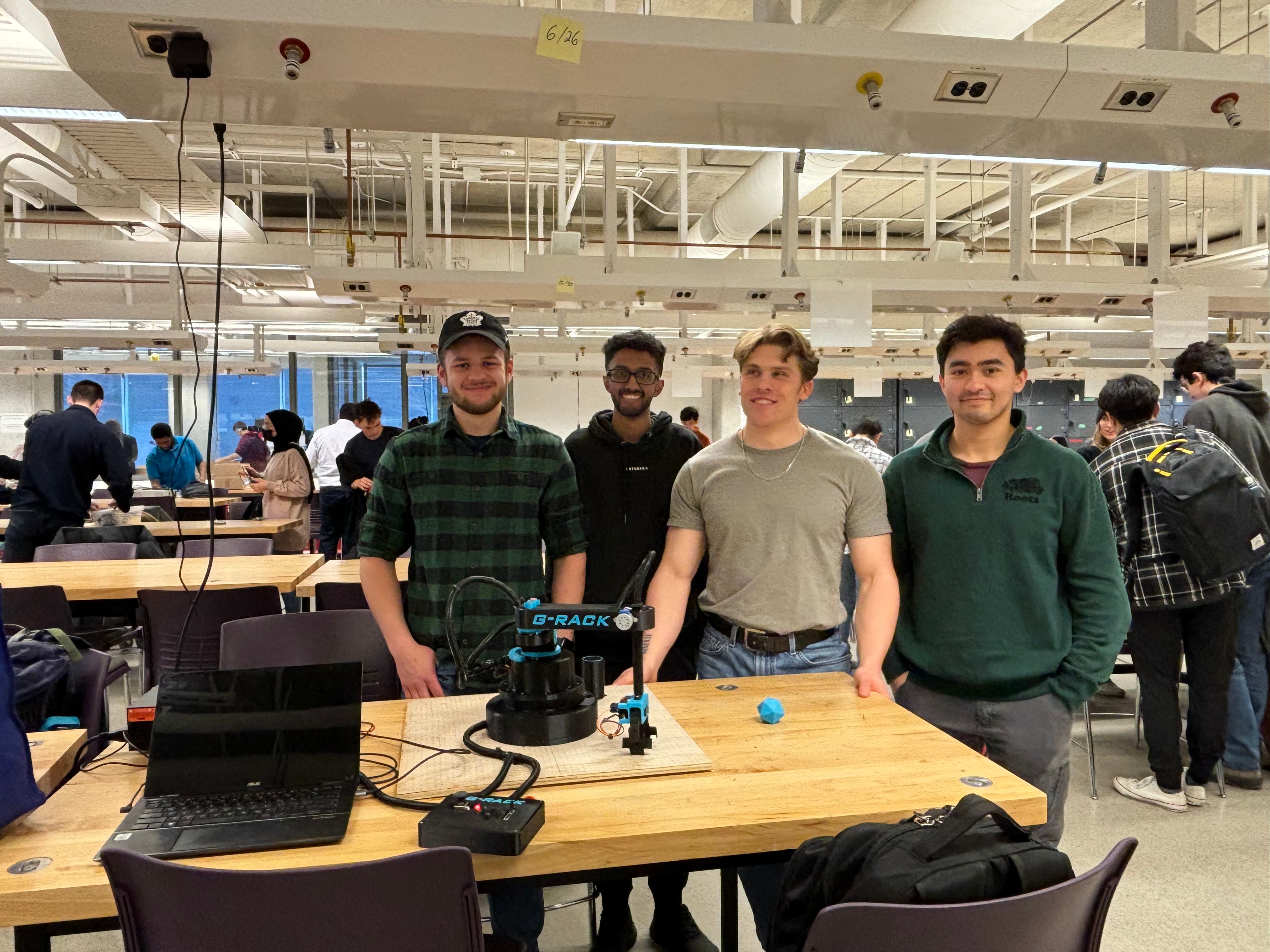
On the far left is Ethan Dau. Ethan’s responsibilities included mechanical design, fabrication and assembly as well as some firmware when he had the bandwidth. Ethan also helped out with project management related tasks.
To the right of Ethan is Varrun Vijayanathan. Varrun was the mechanical lead, responsible for the overall mechanical design and the majority of the CAD and he also did some firmware.
To the right of Varrun is myself. I was the team lead, both for technical and project management related duties. Additionally, I was primarily responsible for developing the firmware and controls for the robot. I also heavily supported the electrical design and was in charge of overall system integration and debugging.
On the far right is Eric Gharghouri. Eric was responsible for the electrical system architecture, electrical fabrication and testing as well as some firmware support.
The Plan
With the team in place and the challenge understood, it was time to start formulating a plan.

The idea we were most interested in was a SCARA style robotic arm. We chose this design since it is common for pick and place applications like this once. However, given the singular nature of the challenge however, the SCARA robot was not the easiest, most effective or most efficient way we could have solved this design problem, but it was the one we were interested in working on. We also considered creating a cartesian robot as well as a direct conveyance system but found them too boring. Our general philosophy for this project was that we wanted to take the path that would result in the maximum amount of learning and give us all valuable design experience.
From the rough sketch, an electrical system architecture was defined.
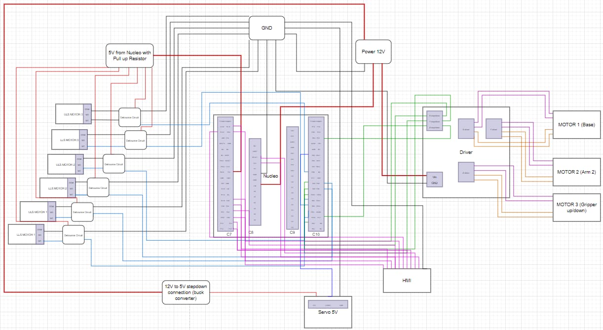
On the left of the diagram there are 6 limit switches, two for each of the axes of motion.
In the center is our microprocessor, which was a NUCLEO-STM32 development board. We chose to use and STM32 because it would give better peripheral access than an arduino for developing drivers.
In terms of actuators, the three axes of motion would all be driven by stepper motors. Stepper motors are cheap and provide precise position control so they were suitable for this project. The end effector actuator was a servo since it was well suited to the requirements of a gripper.
The system would be supplied by 12V which would power the Nucleo and the motors and then a 5V buck was included to drive the servo motor. The stepper motors would be driven by a 4-motor stepper motor driver shield. We planned to interface with the robot via and buttons and joystick which is captures in the HMI (Human Machine Interface) section in the bottom right.
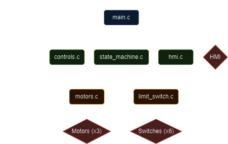
The firmware architecture was designed to be modular and to have proper separation of concerns. The program flow would be that the main program polled the interface using the HMI HAL and when needed, would send position requests to the controls functional layer which would compute the inverse kinematics (IK) and determine the optimal motor deltas to achieve the requested position.
The controls functional layer would then request the motor deltas and desired speed from the motor hardware abstraction layer which would set up and start the timers that drive the motors. All the while the limit switch hall would trigger a hardware interrupt if one of the switches was contacted and update the state machine which would halt the robots operations.
The HMI HAL ended up functioning more like a functional layer since main.c called it directly and it is also where the state machine lived.
Inverse Kinematics
While Ethan and Varrun got started on the CAD and Eric was working on the electrical system, I started developing the inverse kinematics algorithms. I wanted to do these completely from scratch to fully understand the problem.
I started by sketching out the system and deriving the equations for the forward and inverse kinematics. I knew that I wanted the controls functional layer to be able to accept x and y coordinates as commands since that would be the most intuitive later on. My plan was to first implement and test the algorithms in Python and then once the hardware was ready, convert the code to C and move it over to the Nucleo project.
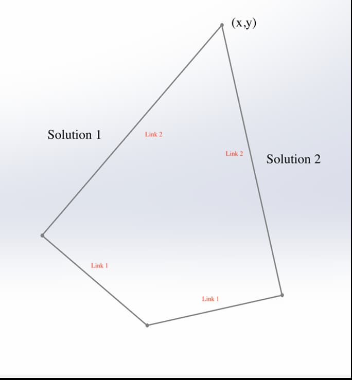
I implemented the IK function in Python and used CAD to validate that it was returning valid angles. I knew that we planned to have a manual control mode for the robot, so I wanted to see how the outputs would respond when receiving incremental position commands. The best way I thought to so this was to create a simple simulation using a Tkinter window. The window would listen for key strokes and allow me to control the x and y position of the end effector with the arrow keys on my computer.
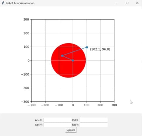
What I discovered is that because our initial design had joint 1 off-center relative to the base, our limit switch positions would not prevent the end effector from colliding with the robot’s base in all of the cartesian quadrants. I also realized we had not accounted for the size of the end effector when choosing our limit switch positions.
To fix the collision problem, I asked the mechanical team to remove the belt drive on link 1 and direct drive it from the concentric center of the base. To account for the end effector, I added in the estimated radius of the end into the simulation and figure out new limit switch angles.
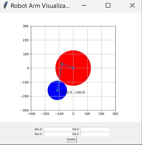
Another thing I discovered from using the simulator was that when requesting incremental positions, sometimes the links would “jump” from the left hand solution to the right hand solution as they crossed the sign threshold of one of the trigonometric functions. To fix this I need to add in logic which would choose the “best” solution from both of the possible solutions.
def motion_request(x, y):

    # ...

    # Check to see if solutions are valid
    soln1_valid = is_valid(sol1)
    soln2_valid = is_valid(sol2)

    # If both are valid, take the shortest path
    if soln1_valid and soln2_valid:
        # This is a very rudimentary way to determine the best path, will need improvement
        delta_sum_1 = abs(sol1[0] - cur_theta1) + abs(sol1[1] - cur_theta2)
        delta_sum_2 = abs(sol2[0] - cur_theta1) + abs(sol2[1] - cur_theta2)
        # Choose the best solution
        if delta_sum_1 < delta_sum_2:
            best = sol1
        else:
            best = sol2
    # If only one solution is valid, take that one
    elif soln1_valid:
        best = sol1
    elif soln2_valid:
        best = sol2
    # Need to determine behavior if neither solutions is valid
    else:
        # Do error stuff
        # Probably just blink the red status LED and ignore the command
        print("Invalid")
        return [robot_state["theta1"], robot_state["theta2"]]

    # Calculate the fastest path that does not move through the restricted angle range
    delta1 = calculate_quickest_valid_path(cur_theta1, best[0], 1)
    delta2 = calculate_quickest_valid_path(cur_theta2, best[1], 2)

    # ...
The code would first check if each solution put the joints into a valid position given the limit switch constraints, if only one solution was valid, the choice was simple.
If both solutions were valid, the one which produced the smallest total delta between the current and target positions was chosen. But even with the best valid solution chosen, the robot might still move through the restricted angle to get to that position so this had to be prevented.
Once I was fairly confident everything was working in Python, I converted the logic to C and implemented the controls functional layer in the Nucleo project and tested with real motors.
Stepper Motor Drivers
While I was developing the IK algorithms, I was also developing the motor drivers in the Nucleo project in parallel so that I could perform the test show in the video above. The motors are driven using hardware timers where the timer ISR steps the motor.
// Motor Objects
Motor motor1 = {
    // X
    .name = "motor1",
    .stepPort = GPIOA,      // D2-PA10
    .stepPin = GPIO_PIN_10, // D2-PA10
    .dirPort = GPIOB,       // D5-PB4
    .dirPin = GPIO_PIN_4,   // D5-PB4
    .dir = CCW,
    .reduction = 1,
    .thetaMin = -160.0 / 180.0 * M_PI,
    .thetaMax = 160.0 / 180.0 * M_PI,
    .isMoving = 0,
};

void TIM3_IRQHandler(void)
{
    if (__HAL_TIM_GET_FLAG(&htim3, TIM_FLAG_UPDATE) != RESET)
    {
        if (__HAL_TIM_GET_IT_SOURCE(&htim3, TIM_IT_UPDATE) != RESET)
        {
            __HAL_TIM_CLEAR_IT(&htim3, TIM_IT_UPDATE);
            StepMotor(&motor1);
        }
    }
}
I allocated a separate timer for each stepper motor so that all of the motors could be run simultaneously and asynchronously. Each motor is defined in a struct which specifies the parameters for that motor. Once I had basic control of the motors, I created a simple API that I could call from other modules to move the motors.
double MoveByAngle(Motor *motor, double angle, double speedRPM)
{
    motor->isMoving = 1;
    if (angle > 0)
    {
        HAL_GPIO_WritePin(motor->dirPort, motor->dirPin, CCW);
        motor->dir = CCW;
    }
    else
    {
        HAL_GPIO_WritePin(motor->dirPort, motor->dirPin, CW);
        motor->dir = CW;
        angle = angle * -1;
    }

    // Gain scheduling setup
    motor->stepsToComplete = (uint32_t)((angle / (2 * M_PI)) * STEPS_PER_REV * motor->reduction);
    // Speed up for first 1/4 steps
    motor->stepsToSpeedUp = 3.0 / 4.0 * motor->stepsToComplete;
    // Slow down for last 1/4 steps
    motor->stepsToSlowDown = 1.0 / 4.0 * motor->stepsToComplete;
    // RPM delta per step
    motor->slope = (speedRPM - MIN_RPM) / (motor->stepsToSlowDown);
    // Start at the min rpm
    motor->currentRPM = MIN_RPM;

    // If we are in manual, set speed to desired speed right away
    if (state.manual)
    {
        motor->currentRPM = speedRPM;
    }
    else
    {
        motor->currentRPM = MIN_RPM;
    }

    float timePerStep = 60.0 / (motor->currentRPM * STEPS_PER_REV * motor->reduction); // Time per step in seconds
    uint32_t timerPeriod = (uint32_t)((timePerStep * 1000000) / 2) - 1;                // Time per toggle, in microseconds

    double angleToComplete = motor->stepsToComplete / STEPS_PER_REV / motor->reduction * 2 * M_PI;
    if (motor->dir == CW)
    {
        angleToComplete = angleToComplete * -1;
    }

    if (motor->name == motor1.name)
    {
        __HAL_TIM_SET_AUTORELOAD(&htim3, timerPeriod);
        HAL_TIM_Base_Start_IT(&htim3);
    }
    else if (motor->name == motor2.name)
    {
        __HAL_TIM_SET_AUTORELOAD(&htim4, timerPeriod);
        HAL_TIM_Base_Start_IT(&htim4);
    }

    return angleToComplete;
}
The function to control the z-axis motor is separate since it made more sense to control that motor based on the desired linear movement of the rack.
First Build
While I had been developing and testing the controls functional layer and making the first implementation of the limit switch abstraction layer, the rest of the team had been working on designing and fabricating the mechanical and electrical systems. Once all the harnesses and shields had been fabricated by Eric and the parts had been designed and 3D printed by Ethan and Varrun, we were ready for our first full system build.
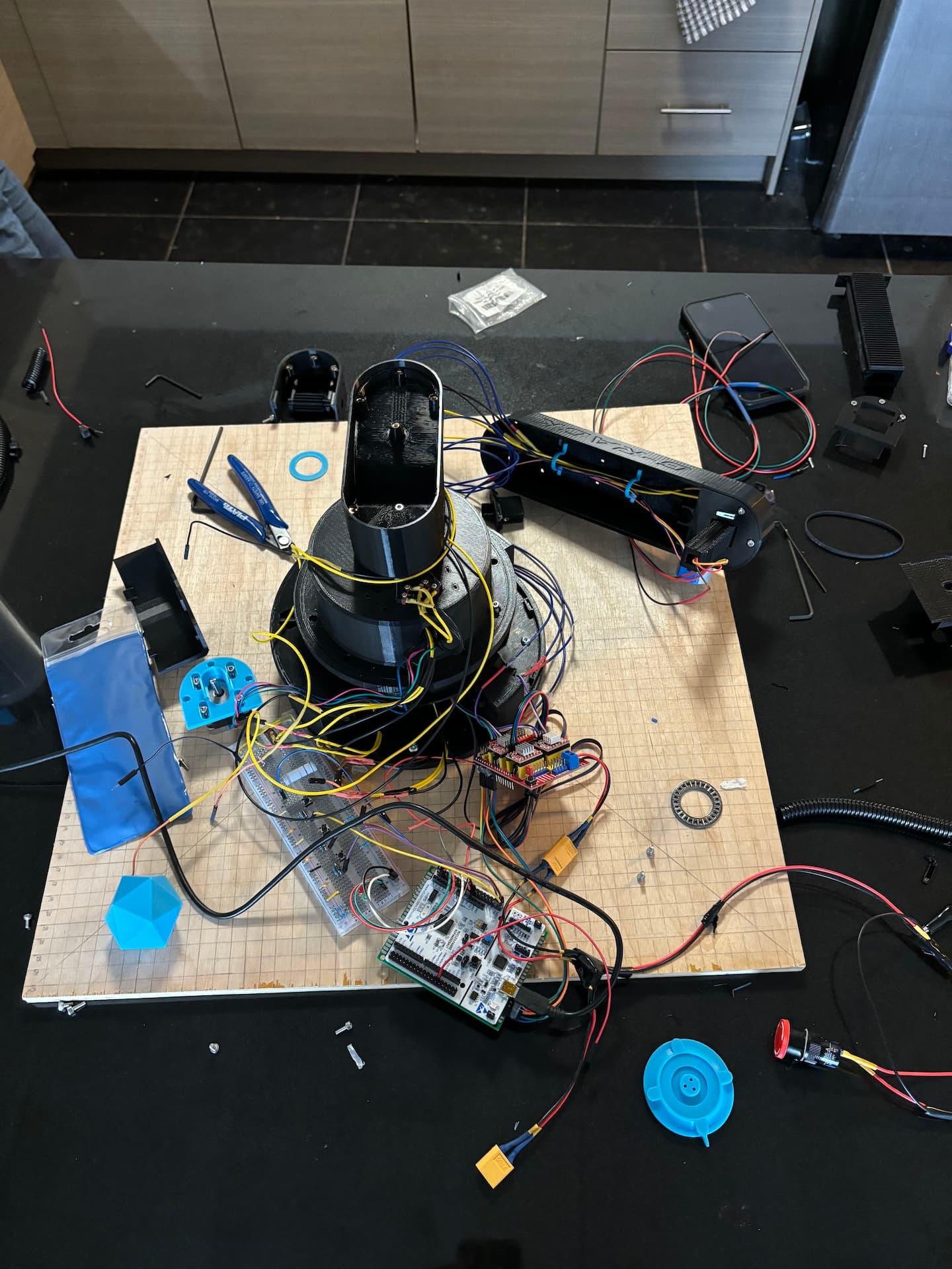
Needless to say it was a messy process and it took much longer than expected. For starters, the harnesses that has been made for the limit switches did not account for the slack required when the robot moved around so they all need to be re-fabricated that day. There was also some tolerance issue with some of the 3D printed parts so the build was blocked while we waited for replacement parts to be printed.
Another issue that we found was that when the robot contacted a limit switch, it triggered many times due to the mechanical bouncing of the switch and sometimes the switch would false trigger while the motors were running, causing the robot to stop unexpectedly. Additionally, sometimes the triggering one limit switch would also trigger one of the other limit switches.
Limit Switches
Originally I had tested the limit switches on a breadboard and had just put a capacitor across the switch to act as a very simple debounce circuit. This had worked for me in previous projects and worked well initially. I developed the limit switch HAL with this configuration and had perfect reliability during my testing.
The limit switch HAL configured the pins and routed them to hardware interrupt handlers. In the interrupt handlers, the state machine would be updated which would break the motors out of their stepping loops.
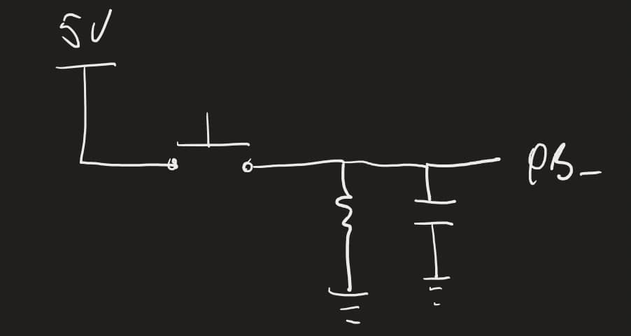
Given that the limit switches worker perfectly during my testing, I was confident they would work during the first build, but when we built up the system, we discovered the issues mentioned above. I was very confused at this point, because a circuit which seemed to have been working perfectly, now had all these erratic behaviors. I wasn’t able to figure out the issue during the first build work so I took the robot home to continue working on it.
What I found was that even when connected to the full system, the issues only occurred when the switches were connected to the bread board with long wires. I could not reproduce the issue under any circumstances with shorter wires.
What I believe was happening is that the longer wires were both acting as giant antennas for noise and also the inductance of the wire was cancelling out the debouncing effect of my capacitor and potentially creating an oscillator. I found that using larger resistors or capacitors could improve the issue but not fully eliminate it.
After doing some research on the issue, I came across a better but slightly more complicated debounce circuit which used two resistors and a diode to control the charge and discharge of the capacitor.
Z-Axis Problems
Anther issue that we ran into was that our z-axis rack and pinion was incredibly slow. We could only move the rack at a painfully slow speed before the motor would stall and at sometimes the mechanical friction in the rack would stall the motor even at slow speeds.
Initially, we thought we would need a larger stepper motor, but we did not want to go down this route as adding a higher torque stepper motor would increase the weight at the end effector and would negatively impact the rest of the system. Instead, we decided to attack the problem from every angle.
Ethan and Varrun redesigned the rack to be thinner and printed it with less infill and a hollow core to make it as light as possible. They also redesigned the assembly with tighter tolerances to reduce the play in the rack and decrease the chance of the teeth binding.
On the firmware side, I switched the stepping scheme from 1/8th stepping to full stepping to get the maximum amount of torque out of the motor. I also found through testing that the motor could maintain higher speeds, but only if it ramped up to them. To make use of this, I added in gain scheduling into the motor HAL.
void StepMotor(void)
{
    // ...

    if (motor->stepsToComplete > motor->stepsToSpeedUp)
    {
        motor->currentRPM += motor->slope;
    }
    else if (motor->stepsToComplete < motor->stepsToSlowDown)
    {
        motor->currentRPM -= motor->slope;
    }

    // Change the timer period based on the current rpm
    float timePerStep;
    if (motor->name == motorz.name)
    {
        timePerStep = 60.0 / (motor->currentRPM * Z_STEPS_PER_REV * motor->reduction); // Time per step in seconds
    }
    else
    {
        timePerStep = 60.0 / (motor->currentRPM * STEPS_PER_REV * motor->reduction); // Time per step in seconds
    }
    uint32_t timerPeriod = (uint32_t)((timePerStep * 1000000) / 2) - 1; // Time per toggle, in microseconds
    // Set the new timer period
    if (motor->name == motor1.name)
    {
        __HAL_TIM_SET_AUTORELOAD(&htim3, timerPeriod);
    }
    else if (motor->name == motor2.name)
    {
        __HAL_TIM_SET_AUTORELOAD(&htim4, timerPeriod);
    }
    else if (motor->name == motorz.name)
    {
        __HAL_TIM_SET_AUTORELOAD(&htim7, timerPeriod);
    }

    // ...
}
When a motor command was called, the gain schedule would be calculated and added to the motor struct. Each time the timer ISR fired, a new timer period would be calculated depending on how far through the desired motion the motor was and then the timer period would be updated.
The combination of these hardware and software changes allowed us to get acceptable and reliable performance from our z-axis assembly
Sag and Mechanical Play
As the deadline for the symposium was approaching, we were running into two issues with the mechanical system, sag and play.
The sag was coming from the joints which were deforming over time causing the plastic housing around the thrust bearings to come into contact, adding a ton of friction to the system. This additional friction was causing our motors to slip or our belt to skip, ruining any kind of accuracy.
The belt tensioner would also deform over time which would cause the belt to skip more easily, and also meant that there was a lot of play in link 2 which meant the end effector was not ending up in the correct position.
Adding in the gain scheduling discussed earlier helped to mitigate both of these issues. For the sag, the ramp at the beginning of the motion made the system more tolerant to the additional friction. For the play, the deceleration at the end of the motion helped the link end up where it should be more often.
But we were not satisfied with this solution, the system was not robust enough. After some brainstorming, we decided to do an emergency redesign of joint 1 which is where the majority of the sag was occurring. We greatly increased the diameter of the joint which meant would could get more plastic and larger fasteners through the radial bearing of the joint and apply more vertical clamping force to prevent the sag.
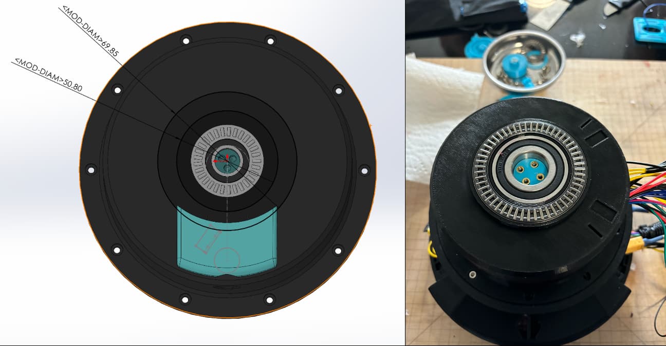
We also added thrust washers to both sides of all of the thrust bearing to reduce the friction. Additionally, the belt tensioning plate was made thicker and printed out of solid plastic to reduce the chance of deformation.
Additional Features
With the hardware pretty much locked in, I added in a couple of last minute firmware features for the demo day.
HMI
Ethan an Eric has worked together to implement the pieces necessary for the manual control of the robot. Eric designed and fabricated the electrical system while Ethan did the mechanical design and developed the HMI HAL.
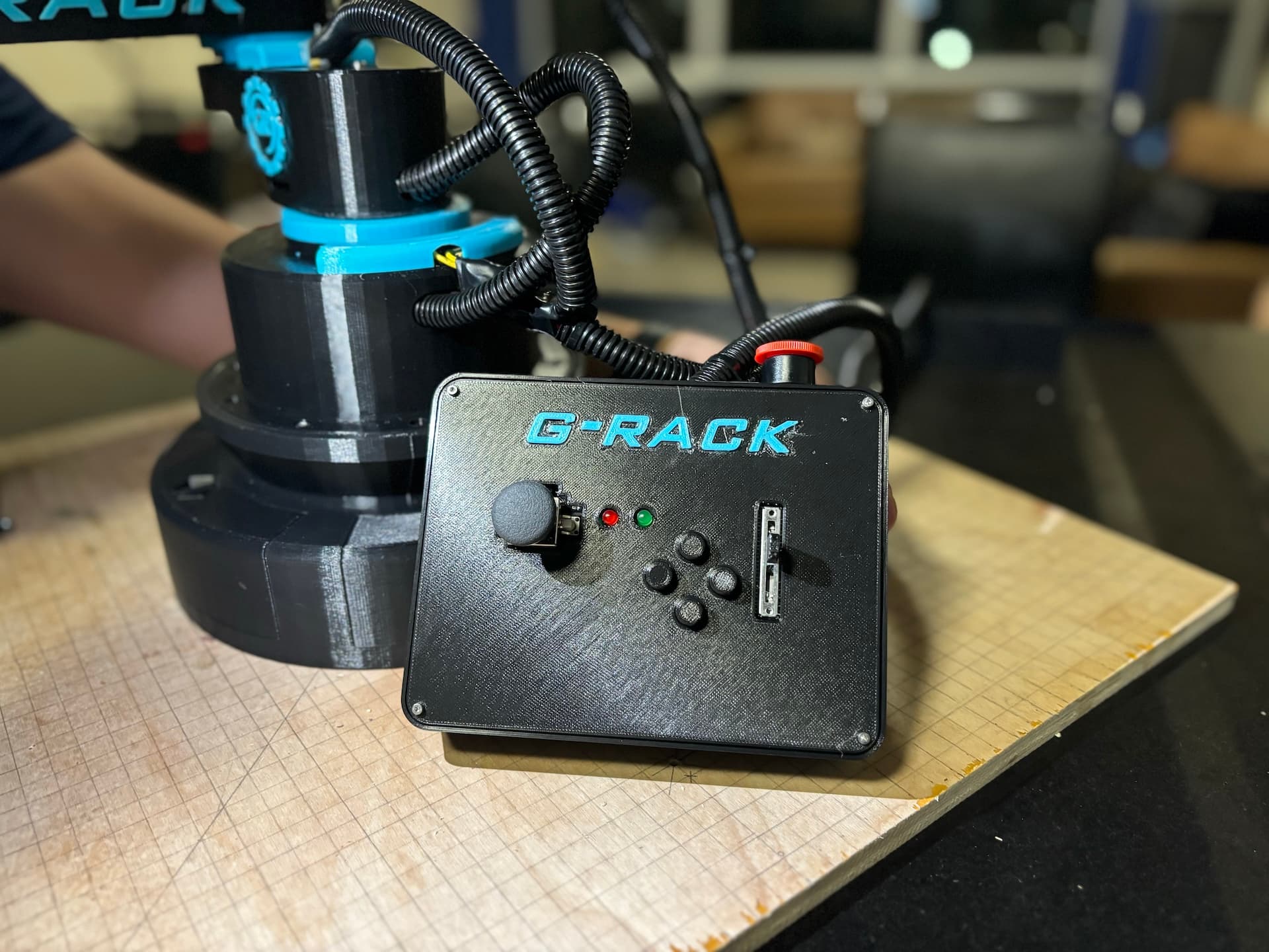
The HMI included a joystick (consisting of two potentiometers and a button), 4 buttons push buttons, a linear pot and two LEDs. The joystick was used to control the x and y position and the joystick button was used to acuate the gripper.
The linear pot was directly mapped to the position of the z-axis while the LEDs indicated system status and were synced to the status LEDs on the robot. With this, all that was left was to add the logic that allowed the robot to be controlled manually.
void Manual_Mode(void)
{
    gripButton.latched = 0;
    while (1)
    {
        // Read user inputs
        readAndFilter(&xPot);
        readAndFilter(&yPot);
        readAndFilter(&zPot);

        Manual_Gripper();
        Manual_Z();
        Manual_XY();

        // Hold the loop while any of the motors are moving
        if (motor1.isMoving || motor2.isMoving || motorz.isMoving)
        {
        while (motor1.isMoving || motor2.isMoving || motorz.isMoving)
        {
            // Read user inputs
            readAndFilter(&xPot);
            readAndFilter(&yPot);
            readAndFilter(&zPot);

            Manual_Gripper();

            while (motor1.isMoving || motor2.isMoving)
            {
            HAL_Delay(1);
            }

            Manual_XY();
        }
        }
        else // if nothing is happening, delay the loop
        {
        HAL_Delay(20);
        }

        if (!HAL_GPIO_ReadPin(homeButton.port, homeButton.pin))
        {
        HomeMotors();
        MoveTo(-150.0, 150.0, 5.0);
        while (motor1.isMoving || motor2.isMoving)
        {
            HAL_Delay(1);
        }
        }

        // Return to automatic mode
        if (HAL_GPIO_ReadPin(autoManButton.port, autoManButton.pin) == GPIO_PIN_RESET)
        {
        HAL_Delay(500); // So button isn't "double-pressed"
        return;
        }
    }
}
The code reads the user inputs, and in the case of the potentiometers, low-pass filters the readings. For the joystick, the position of the joystick would be mapped to a motor speed and then an incremental motor command would be issued issued.
For the z axis, the code checks to see if there is an appreciable delta between the axis position and the corresponding linear pot position and sends a move command to the motor if necessary.
The code also monitors the state of the buttons to see if the gripper should be actuated or if the user want to home, reset or change back to automatic mode.
The polling and processing of commands happens synchronously since all of the motor control and limit switch behavior is handled asynchronously.
Test Mode
Before the symposium, I quickly implemented a test mode which would run the hard coded movement commands required to complete the design challenge. I spent some time tweaking positions commands and the speed to get the most reliable performance.
I also added a repeatability mode where the robot would continuously perform the test, home and then perform the test again. The purpose of the test mode and repeatability mode were to validate the design objectives (accuracy and repeatability) that we had selected at the beginning of the term.
Path Planning
Lastly, I added in some rudimentary path planning to make the motion of the robot look smoother.
void MoveTo(double x, double y, double rpm)
{
    // ...

    // Path planning
    double rpmDelta, rpm1, rpm2;
    double magDelta1 = fabs(delta1);
    double magDelta2 = fabs(delta2);
    if (delta1 > delta2)
    {
        rpmDelta = rpm * ((magDelta1 - magDelta2) / (magDelta1 + magDelta2));
        rpm1 = rpm + rpmDelta;
        rpm2 = rpm - rpmDelta;
    }
    else
    {
        rpmDelta = rpm * ((magDelta2 - magDelta1) / (magDelta1 + magDelta2));
        rpm1 = rpm - rpmDelta;
        rpm2 = rpm + rpmDelta;
    }

    // Ensure RPMs are reasonable
    if (rpm1 > MAX_RPM)
    {
        rpm1 = MAX_RPM;
    }
    else if (rpm1 < MIN_RPM)
    {
        rpm1 = MIN_RPM;
    }
    if (rpm2 > MAX_RPM)
    {
        rpm2 = MAX_RPM;
    }
    else if (rpm2 < MIN_RPM)
    {
        rpm2 = MIN_RPM;
    }

    // ...
}
All this code does is try and make the motors complete their required motions in the same amount of time, by adjusting the rpms of the motors from the requested speed.
I made this change because I thought it looked a bit janky when only one of the motors was moving and the other was sitting idle. This simple change greatly improved the perceived quality of the robot control.
Symposium
Putting the finishing touches on the robot and getting everything ready for the symposium was a grind. We worked from 9am to 12am the day before and then got together again at 6am to finish putting it all together before heading over to the school at 8am.
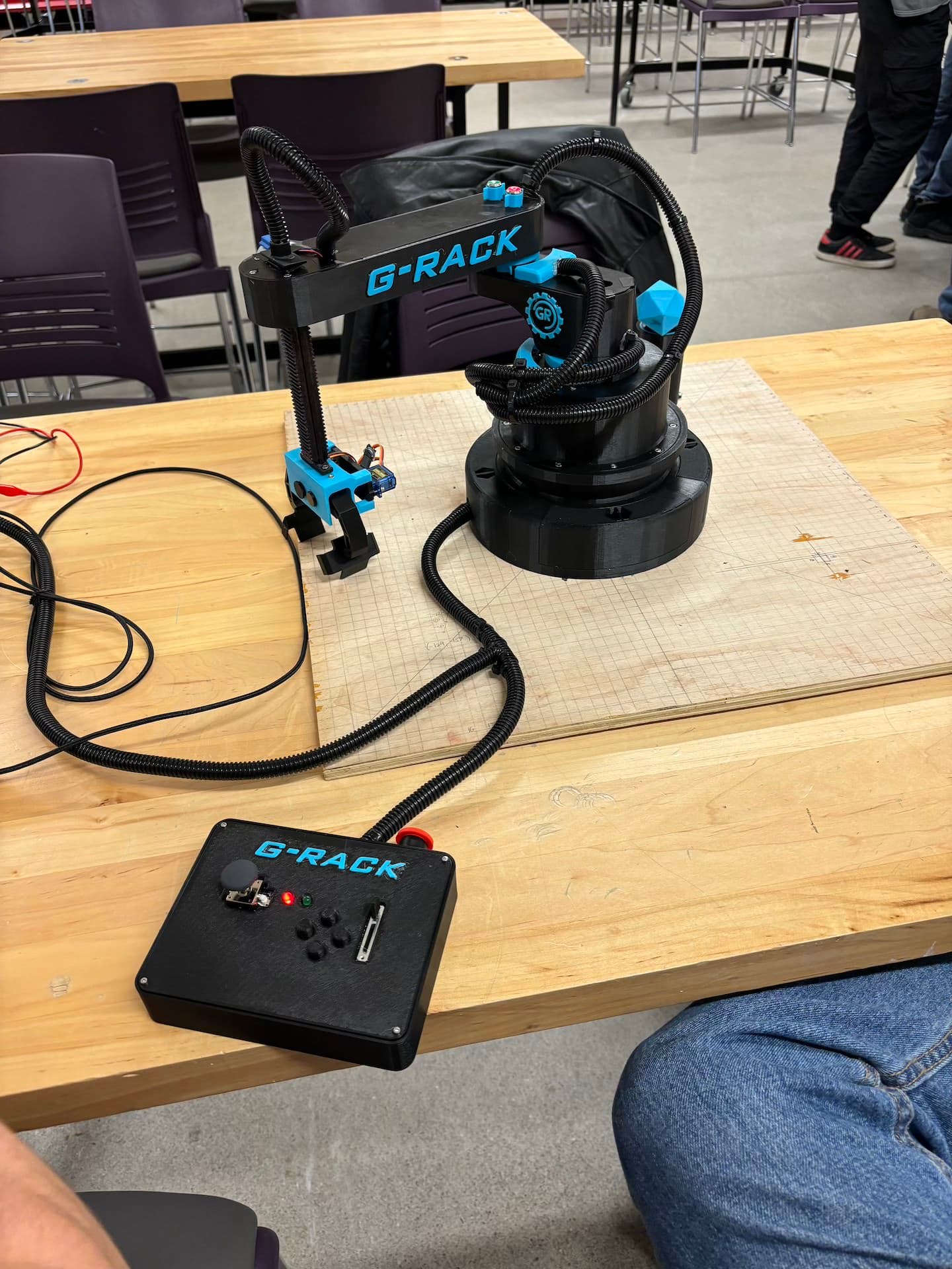
We ended up getting everything together just in time and we were able to show up with a project we were all proud of. Our classmates were very impressed and we got great feedback from the judges.
As part of the symposium presentation and our final report, we had to show proof that our design meet requirements of the design objective we chose at the beginning of the term.
For the accuracy validation, we needed to show that our robot was capable of completing the test and placing the 50x50mm dice within a 60mm radius target.
For the repeatability validation, we needed to show that our robot could get the dice onto the platform successfully 10 times in a row without failure.
Reflection
This project ended up being a lot of hard work but it was a lot of fun and we were really happy with the result. Through this project, I got to learn how to work with STM32’s and implement some basic robot control algorithms on a real system. I also got the opportunity to architect the project and manage a collaborative code space. Overall, this project was a great learning experience and I’m glad we decided to try and do as much as we could from scratch and fully understand the problem.