Beer Can Counter
Two of my best friends, Jaden and Greg, recently bought a house together. The house came equipped with a man-cave garage, so naturally, that’s where we gravitate to when we hang out there.
Jaden and Greg asked me if I could make something that could count how many beer cans were being crushed by their can crusher.
This project is the answer to that request.
Mechanical Design
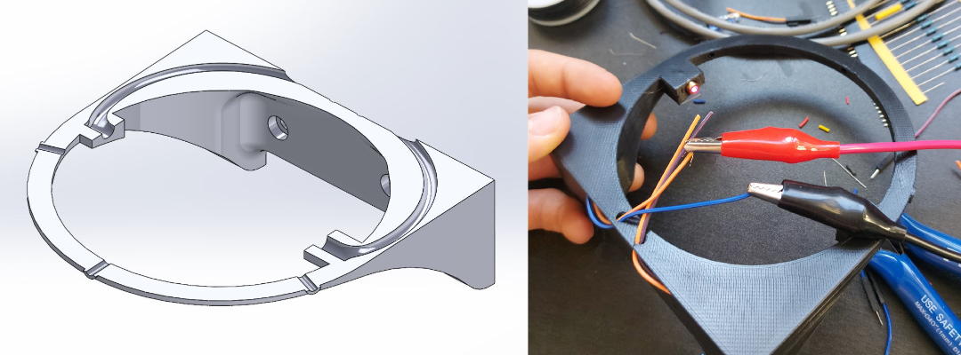
The can collector consists of two parts to make 3D printing feasible.
Below you can see a channel was cut through the bottom portion of the catcher. This channel is used to route the wires from the laser diode and photo-resistor to the back of the model where it is soldered into the harness which runs up to the electrical box. The photo-resistor is recessed into the part to minimize the effect of ambient light on its resistance, and to deliver consistent performance in different lighting environments.

Hardware Design
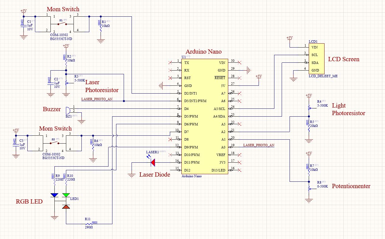
Schematic created for reference in Altium.

Design Highlights
- Momentary switches have debouncing capacitors which act as low pass filters on the switch signals
- There is a cap across the laser photo-resistor, to create a low-pass filter on the photo-resistor output. The goal of this setup was to be able to generate an external interrupt each time a can intercepts the laser.
- The laser photo-resistor can also be read by an analog pin. This was for tuning the initial setup and finding a resistor that would be suitable to generate a digital signal when the laser beam was broken.
- The light photo-resistor produces an analog signal that is representative of the light level in the room. Its signal is used to determine if the device should be on or off.
Code
C++ running on an Arduino Nano
void loop() {
  // Halts program while the lights are off.
  lights_off_global = lights_off();
  // lights_off returns 1 when lights are supposed to be off
  while (lights_off_global) {
    lights_off_global = lights_off();;
  }

  // If a can has passed through the laser
  if (can_detected) {
    beers = update_count(); // Update the beer count
    meme_detector(beers);   // Check for milestones
    update_screen(beers);   // Update the screen with new count
    can_detected = 0;       // Reset detection bool

  }

  // If the reset button has been pushed
  if (reset_requested) {
    // Process reset request
    reset_req();
  }

  // Enables/disables RBG LED cycle
  if (digitalRead(BUTTON)) {
    RGB_LED_on = !RGB_LED_on;
    while (digitalRead(BUTTON));
  }

  // If the LED is on, cycle through colour
  if (RGB_LED_on) {
    update_LED();
  }
  else {
    RGB_LED(0,0,0);
  }
}
- Reads photo-resistor and determines if lights in the room are ON/OFF
- Low-pass filter on photo-resistor output
- photo-resistor output is connected to external interrupt which triggers count
- Count is stored in EEPROM
- Check to see if number is a funny number
- User can press reset button to reset the device
Reflection
I really enjoyed working on this project. Projects that are built for someone else are my favorite type of projects because they give me extra motivation to work on them and it removes any second guessing I might have about whether or not I should spend my time doing this project.
The goal of this project was to get it done as quickly as possible so I could start working on my resume and portfolio before the next school semester started. Though my focus was speed, my criteria for the device was that It needed to look professional enough to fit in, in my friend’s man cave and it needed to work 100% reliably.
I have made things in the past where the code sometimes didn’t work due to timing errors or lack of proper control code and it is super frustrating. Since I am going to be handing this project off to someone as a gift, this couldn’t be the case. I used what I had learned in my past work terms to make this project more robust. I made use of hardware interrupts, hardware filters, and code filters to make the user interface with this device as seamless as possible.
I have to say, I am extremely happy with how well the laser detector works. I started this project with an off-the-shelf motion sensor but it was too unreliable and hard to control so I came up with the idea to make my own. I really wasn’t sure if it would work, I didn’t know if I would be able to generate a digital signal suitable for use with a hardware interrupt using this analog setup.
For the mechanical engineering, I wanted things to fit together nicely and have a professional appearance. That’s why instead of using nuts or threading the bolts directly into the plastic, I used heat-set threaded inserts where ever a metric fastener was used. I’m really glad I added these in as it makes the project look and feel a lot more professional. I also love the way the metal strain reliever on the bottom of the box looks, it gives the box a more industrial aesthetic. I got the idea for this while doing some electrical work installing a new industrial ceiling fan.


