A PCB Christmas
While on my first internship as a hardware designer, I decided that for Christmas I would showcase my new skills and create a cool gadget for all my friends and family.
Each device was loaded with 3 songs with one song being specific to the recipient. The song being played in the video is Silent Night.
Hardware Design
Design Highlights
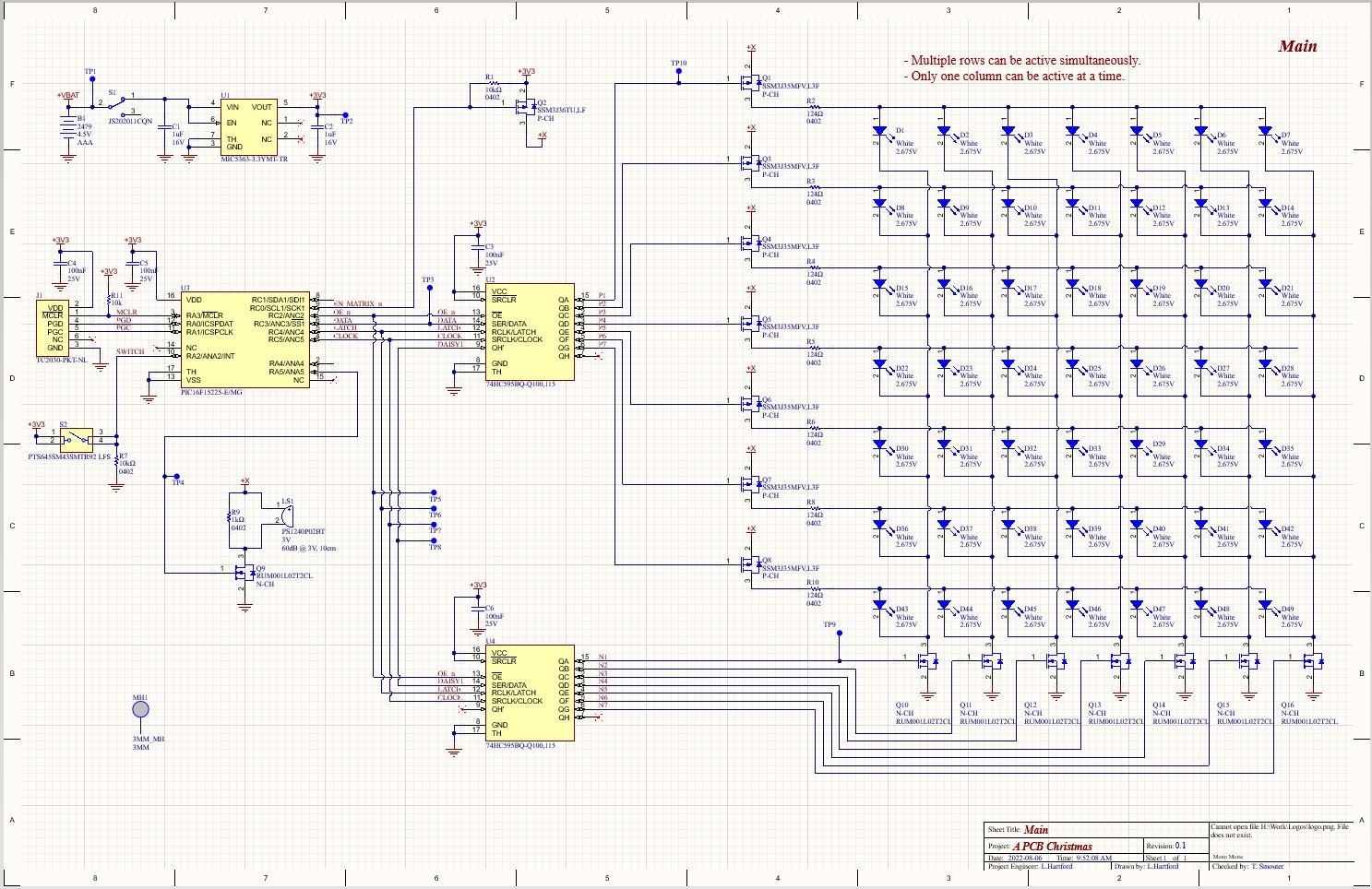
- The main feature of this design is the 7x7 LED matrix used to control the 49 LEDs on each board.
- The MOSFET are controlled by two shift registers, one for the high side and one for the low side.
- The microcontroller I chose to use for this project is a 16-pin, QFN PIC Microcontroller. PIC is a family of embedded microcontrollers made by Microchip. These microcontrollers are really nice to work with because they are usually packed with peripherals and are very configurable.
- Music is played by sending by sending different PWM frequencies to the gate of the driving MOSFET, which changes the frequency of sound emitted from the buzzer.
Low Power Design
- 3x AAA batteries -> 4.5V -> 3.3V LDO
- A 3-position toggle switch is in series with the batteries and the LDO. This allows the batteries to be completely disconnected from the device, removing power loss from leakage or quiescent current when the device is stored.
- While the device is ON, A P-CH load switch is able to disconnect the LED matrix from the 3V3 rail in order to reduce the total amount of leakage current.
- When not in use, the PIC microcontroller goes to sleep and waits for an external interrupt from the button. The level shifters are placed into a high impedance, low quiescent current state while the microcontroller is asleep.
Layout
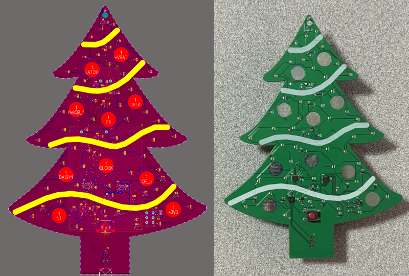
- 2-layer PCB
- The board outline was drawn in SolidWorks and then imported as a DXF.
- Large copper pads used to create ornaments which doubled as test-points during development.
- Thick curved lines to the silk-screen layer to create streamers on the Christmas tree
Code
The firmware for this project works but it is extremely inefficient and has some bugs in it. I wrote this code in a furry and did not have time to think about the best way to write the code and so this seemingly simple program occupies almost 1300 lines of code and all of my microcontroller’s flash memory.
Architecture Notes
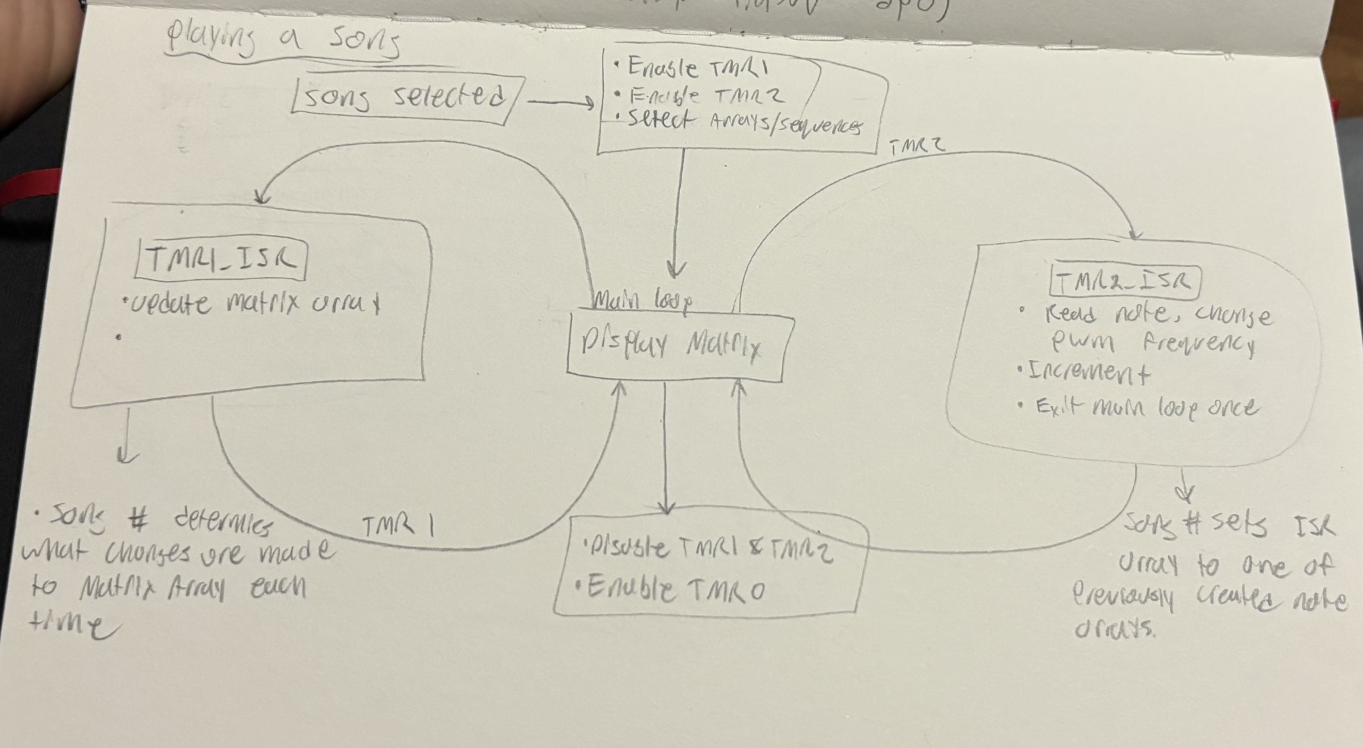
Playing Songs
- The pitch of the buzzer is determined by the frequency of the PWM signal being sent to the gate of the MOSFET.
- The PWM frequency can be controlled by changing the pre-scaler and period of TMR2.
- The pre-scaler is essentially how fast this timer runs relative to the system clock, and the period is the number cycles before the timer rolls over and changes the state of the PWM signal.
- Each pre-scaler value is only suitable to produce a particular octave range of notes.
void TMR1_ISR_(void)
{
    count++;    // Increment beat counter

    // Update the silent night LED matrix.
    if (silent_night_playing) {
        if (count < 24 || ((count > 48) && (count < 96))) {
            if (last_note != silent_night[count]) {
                for (int i = 0; i < 7; i++)
                {
                    uint8_t lights = light_array[i] >> 7;
                    light_array[i] = (light_array[i] << 1) + lights;
                }
            }
        }
        else if (count > 119 && (last_note != silent_night[count])) {
            for (int i = 0; i < 7; i++)
            {
                light_array[i] = (light_array[i] << 1) + 1;
            }
        }
        else if (count < 120) {
            for (int i = 0; i < 7; i++)
            {
                uint8_t lights = light_array[i] >> 7;
                light_array[i] = (light_array[i] << 1) + lights;
            }
        }
    }
    // ...
}
- The BPM of the music is determined by the TMR1 interrupt service routine which sets the state of the buzzer and LED matrix.
Other Notes
- I used the SPI peripheral as an easy way to clock bits into the shift registers.
- The momentary switch is connected to an external interrupt which can wake the device from sleep or disrupt a song sequence.
Mechanical Design
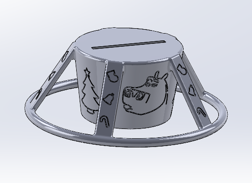
The designs on the stand were created by importing pictures into the sketches, carefully outlining the pictures with splines, and then cutting them out as thin features. The stand friction fits onto the bottom of the PCB and allows the PCB to stand upright.
Concept Sketches

Reflection
Overall, I would not consider this project a major success. In the end, I ended up gifting a device that had bugs and robbed me of nearly all of my free time for almost a month. This was a lesson in time management. I assumed because the idea seemed so simple, playing songs and lights on a custom PCB, that I thought I would be able to complete this project in a month without issue. I wish I had started this project in September instead of November, but we live and learn.
One thing that could have significantly improved the functionality of the code would have been including a capacitor across the switch to low-pass filter the signal. Since I am using this button as an input to an external interrupt peripheral on the controller, I can’t really filter the signal in the software. This resulted in the device occasionally reading multiple presses during a single button press which made it frustrating to use.
The way I stored the song data was also very inefficient. Instead of using one byte to store multiple notes or storing the pre-scaler and note in the same byte, I used two bytes for every note. One byte was the note, and the second byte was the corresponding PWM pre-scaler. This resulted in my code taking up 90%+ of the 14KB of flash provided by the microcontroller, depending on the code version.
As I mentioned earlier, I was in an extreme rush to get this project done in time. That is my fault, I started it too close to Christmas. If I were to do this project over again, I would start it months in advance and take some time to think about the most efficient way to store and play the songs on the device. I would also take the time to make the layout a little nicer.


